***Key Concepts in Networking
Prerequisite — Switching Routing
- Basic Networking Principles:
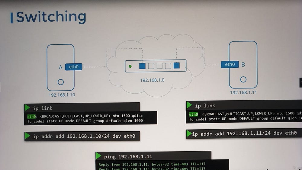
Switches enable communication within a single network by connecting devices.
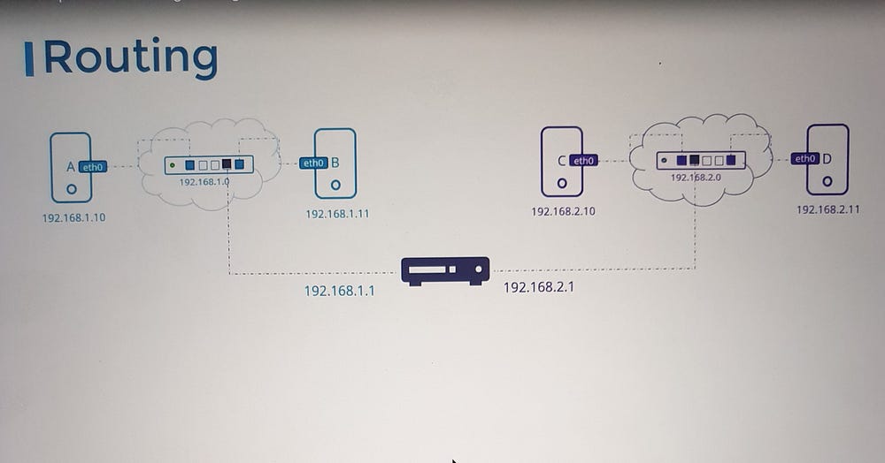
Routers interconnect networks, facilitating communication across different subnets.
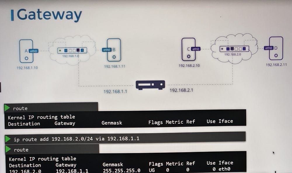
Gateways serve as access points to external networks, including the internet.
2. Linux Networking Tools:
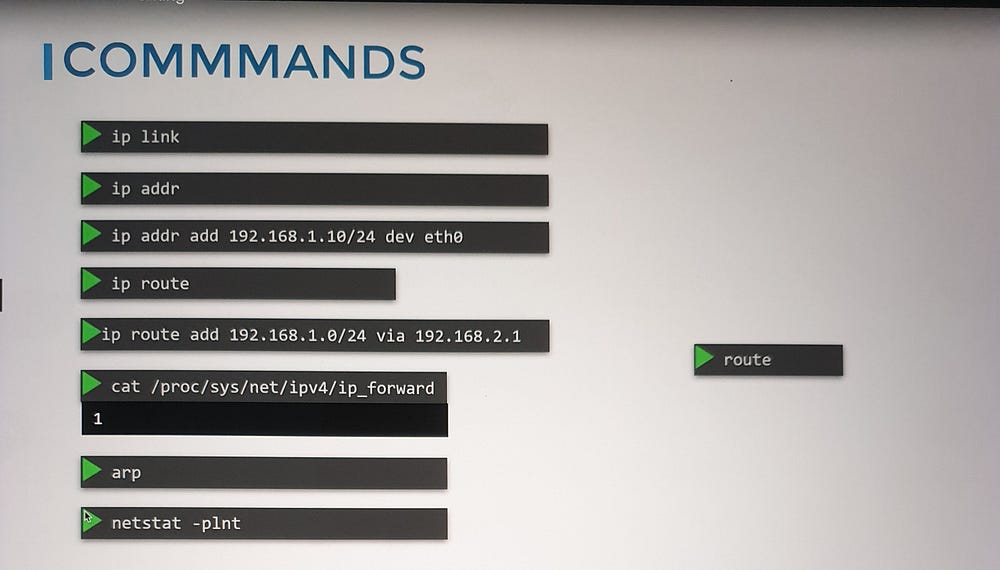
ip link: View and modify network interfaces.ip addr: Display or assign IP addresses to interfaces.routeorip route: View and configure routing tables.
3. Network Namespaces:
- Understand the basics of network namespaces in Linux, which isolate network configurations for applications, ensuring better security and performance.
4. DNS and CoreDNS:
Explore DNS fundamentals and how to configure DNS settings on Linux systems.
Gain a basic introduction to CoreDNS, a DNS server often used in Kubernetes.
5. Routing and IP Forwarding:
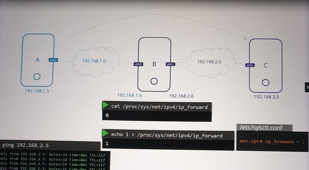
Routing tables define how packets travel across networks. Use commands like
ip route addto add routing entries.IP forwarding in Linux governs the ability to route packets between interfaces. Enable forwarding via
/proc/sys/net/ipv4/ip_forwardfor private networks.
6. Persistent Changes:
- Ensure that network configurations persist across reboots by modifying files like
/etc/network/interfacesor/etc/sysctl.conf.
Connecting Networks
Consider a scenario where systems A and B are connected to one subnet (e.g., 192.168.1.0/24), and systems C and D are on another (192.168.2.0/24). A router links these subnets by assigning IPs on both networks (e.g., 192.168.1.1 and 192.168.2.1). Adding routes on each system ensures seamless communication between them.
For example:
- Add a route on system A
ip route add 192.168.2.0/24 via 192.168.1.1
. Add a reciprocal route on system C
ip route add 192.168.1.0/24 via 192.168.2.1
To further enable communication, configure the router (e.g., system B) to forward packets between its interfaces.
Advanced Scenarios
When scaling networks or connecting to the internet, additional configurations are required:
- Define a default gateway for systems to access external networks
ip route add default via 192.168.1.1
- Manage complex setups with multiple routers by specifying distinct routes for internal and external traffic.

***DNS in Linux for Absolute Beginners
Introduction to DNS
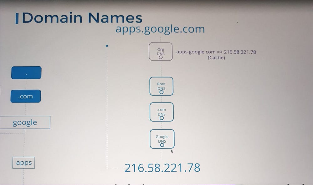
DNS (Domain Name System) is critical for resolving hostnames to IP addresses.
Key Concepts:
1. Local Name Resolution:
Hosts can map names to IP addresses locally using the
/etc/hostsfile.Example: Adding
192.168.1.11 dbto/etc/hostson system A allows referencing system B asdbinstead of its IP address.Note: Entries in
/etc/hostsoverride actual hostnames and can map multiple names to the same system.
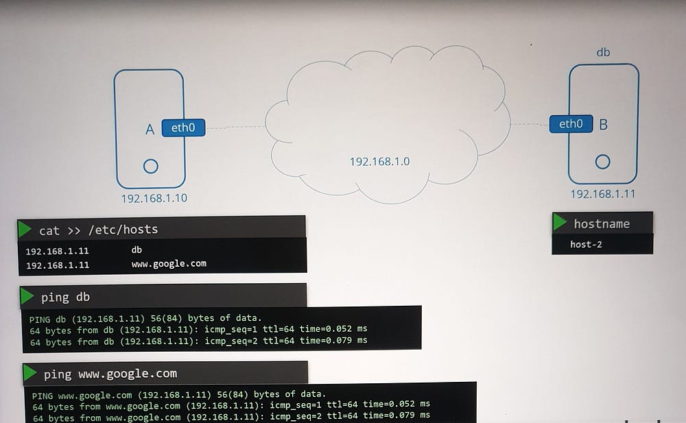
Key Insight:
The /etc/hosts file allows multiple aliases for the same host. For example, system B can also be mapped as www.google.com, fooling system A into treating B as Google's server.
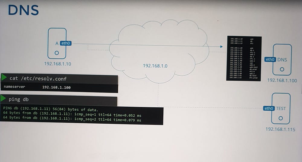
2. Centralized Name Resolution:
For scalable environments, managing mappings in
/etc/hostsbecomes inefficient. A DNS server is used for centralized management.All hosts are configured to refer to a DNS server via the
/etc/resolv.conffile:Example:
nameserver 192.168.1.100.
3. Resolution Order:
Hosts resolve names based on the order specified in
/etc/nsswitch.conf:Default:
files(local/etc/hosts) first, thendns(DNS server).This order can be customized for specific needs.
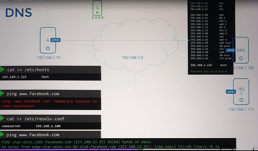
4. Public and Private DNS:
DNS servers in organizations handle internal and external domains:
Internal: Custom domains like
web.mycompany.comordb.mycompany.com.External: Public domains such as
www.google.comare resolved via public DNS servers (e.g., Google's 8.8.8.8).Forwarding: Internal DNS servers can forward unknown queries to public DNS servers.
5. Domain Names and Subdomains:
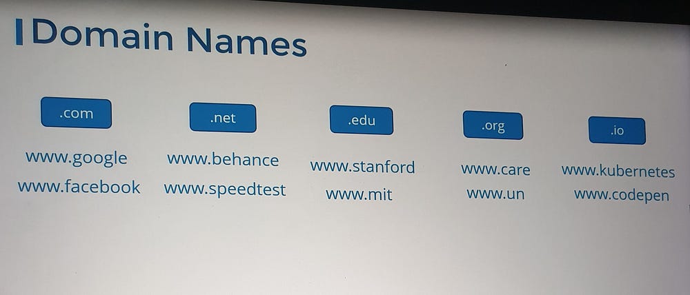
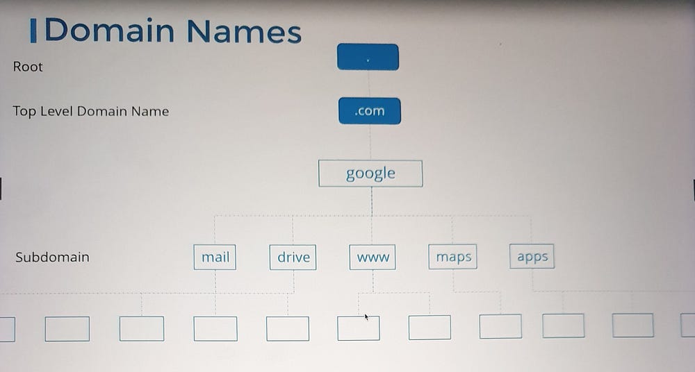
DNS uses a hierarchical naming structure:
Top-Level Domains (TLDs):
.com,.edu,.org, etc.Domain Names:
google.comis Google's domain.Subdomains: Group related services, e.g.,
maps.google.comanddrive.google.com.
6. Search Domains:
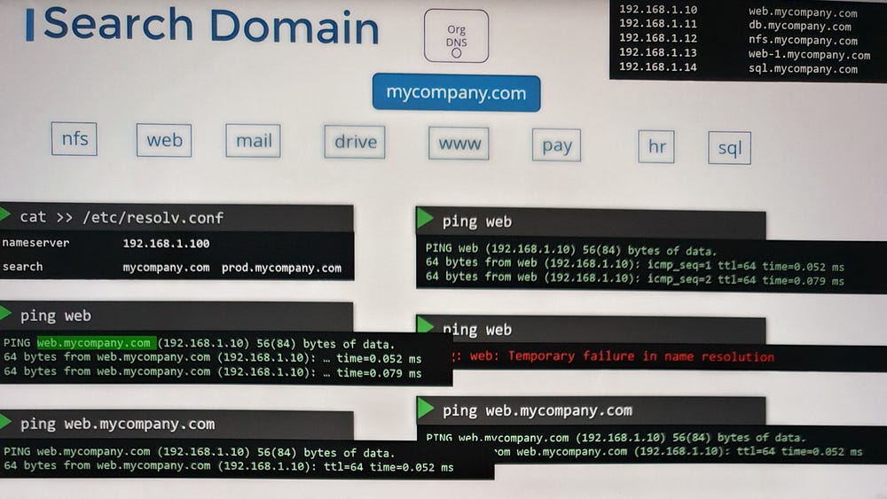
Use the
searchentry in/etc/resolv.confto append domain names automatically:Example:
search mycompany.com prod.mycompany.comresolveswebtoweb.mycompany.comorweb.prod.mycompany.com.
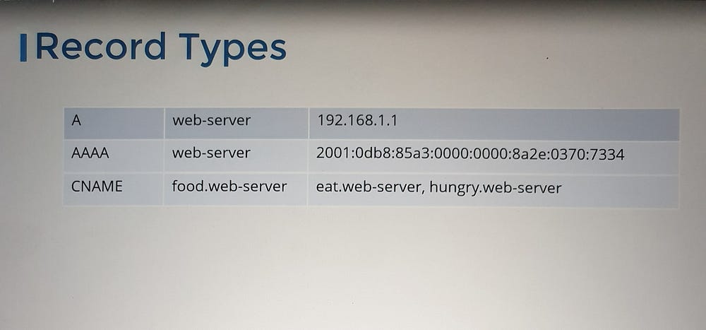
7. DNS Record Types:
A Record: Maps a hostname to an IPv4 address.
AAAA Record: Maps a hostname to an IPv6 address.
CNAME Record: Maps one hostname to another, useful for aliases.
8. Tools for DNS Testing:
ping: Tests name resolution using
/etc/hostsor DNS.nslookup: Queries only DNS servers, bypassing
/etc/hosts.dig: Provides detailed DNS query results.

1
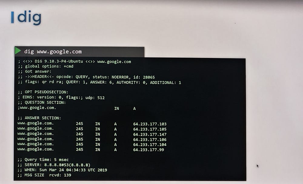
9. Challenges in Large Environments:
DNS servers address scalability issues:
Easier management when IP addresses change.
Cache results for faster lookups.
***Understanding Network Namespaces
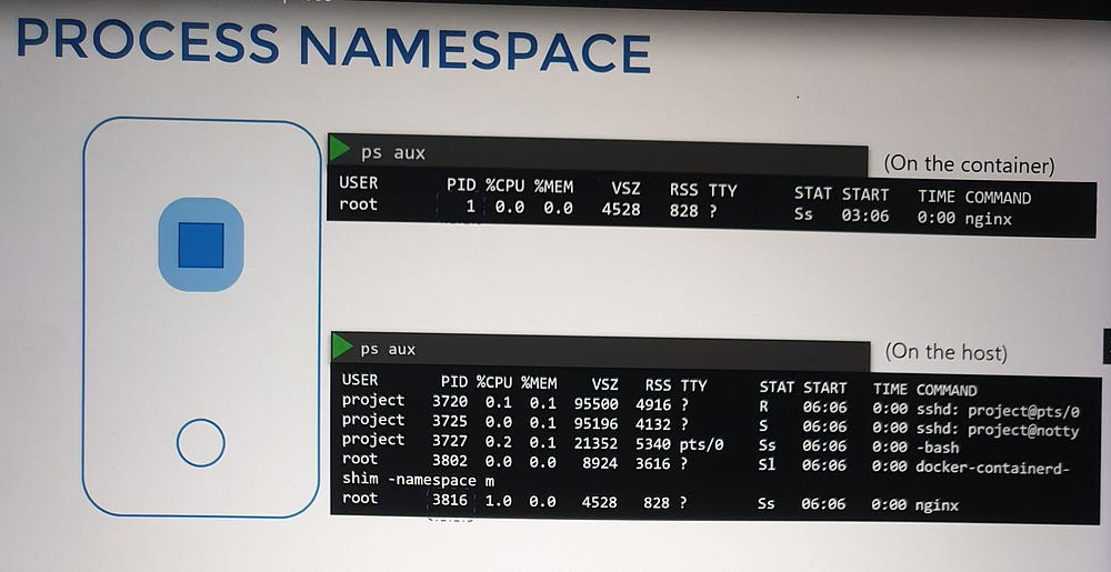
Namespaces are like individual rooms within the house, offering privacy to each child (or process). Each “child” can only see what’s inside their room, while the parent (the host) has visibility across all rooms. In the same way, namespaces isolate processes or containers, ensuring they operate independently from the host and from one another.
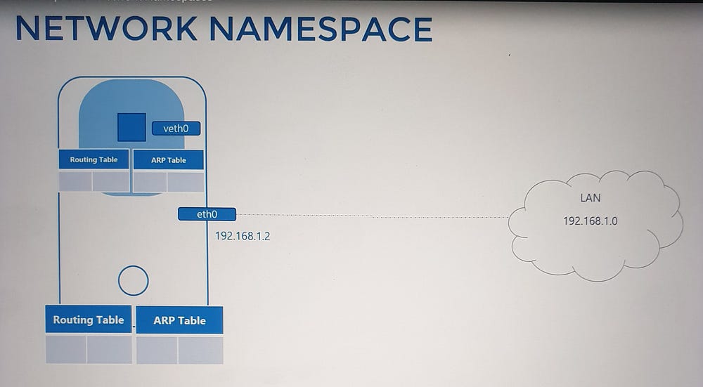
When you create a container, a network namespace is allocated, isolating its network environment. As far as the container is concerned, it operates as if it were on its own host, with no awareness of the underlying host or other containers. The host, however, has complete visibility and control.
Network Namespace Basics
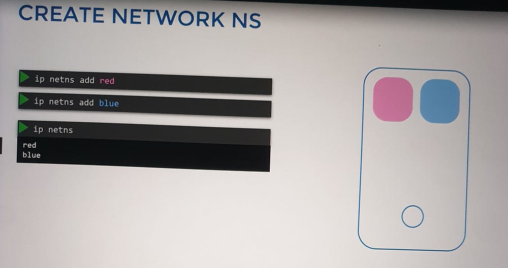
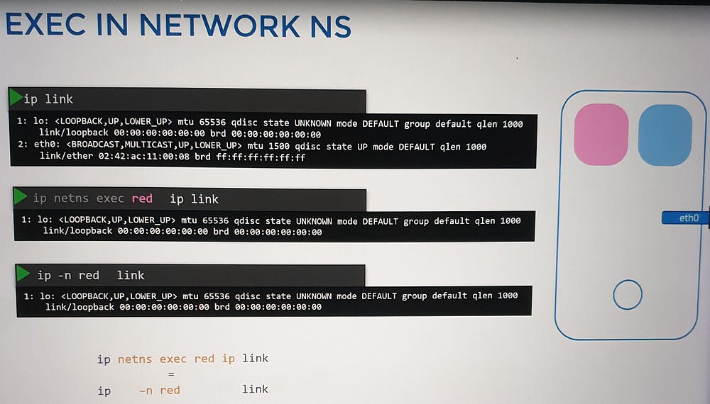
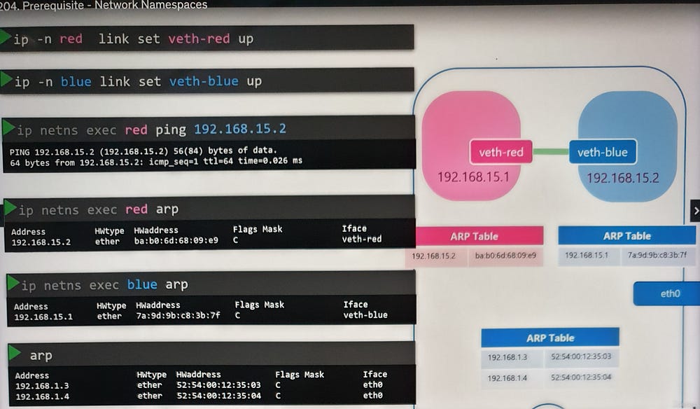
To demonstrate, we use the command ip netns to create and interact with network namespaces:
Create namespaces: Use
ip netns add [namespace_name].List namespaces: Run
ip netns.Execute commands inside namespaces: Use
ip netns exec [namespace_name] [command].
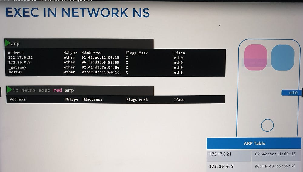
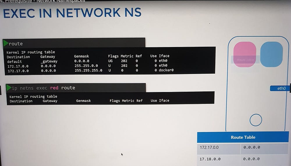
Within a network namespace, you can define virtual network interfaces, ARP tables, and routing rules, fully isolated from the host system.
Connecting Namespaces
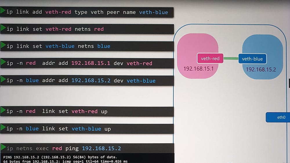
Initially, namespaces have no network connectivity. To enable communication:
Create a virtual Ethernet pair:
ip link add [interface1] type veth peer name [interface2].Assign interfaces to namespaces: Use
ip link set [interface] netns [namespace_name].Configure IP addresses: Assign IPs with
ip addr addand bring interfaces up withip link set [interface] up.Test connectivity: Use
pingbetween namespaces to verify the setup.
Scaling with Virtual Bridges
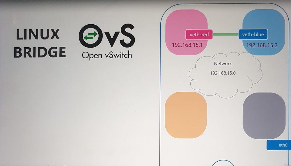
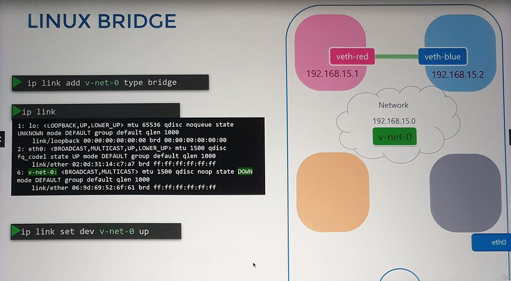
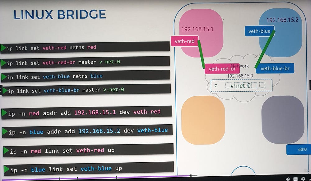
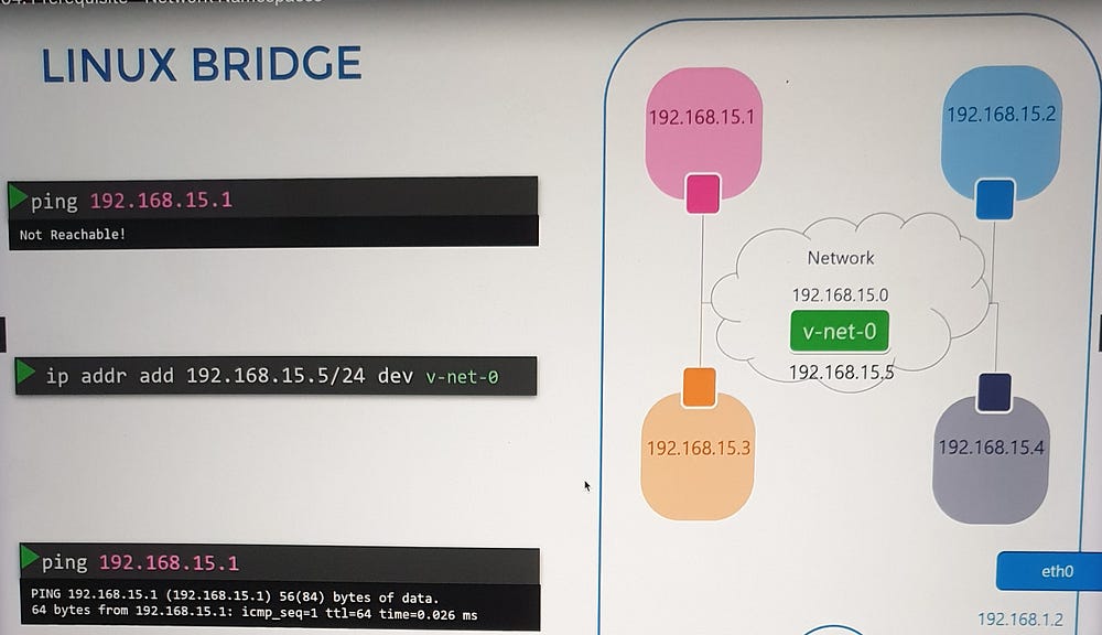
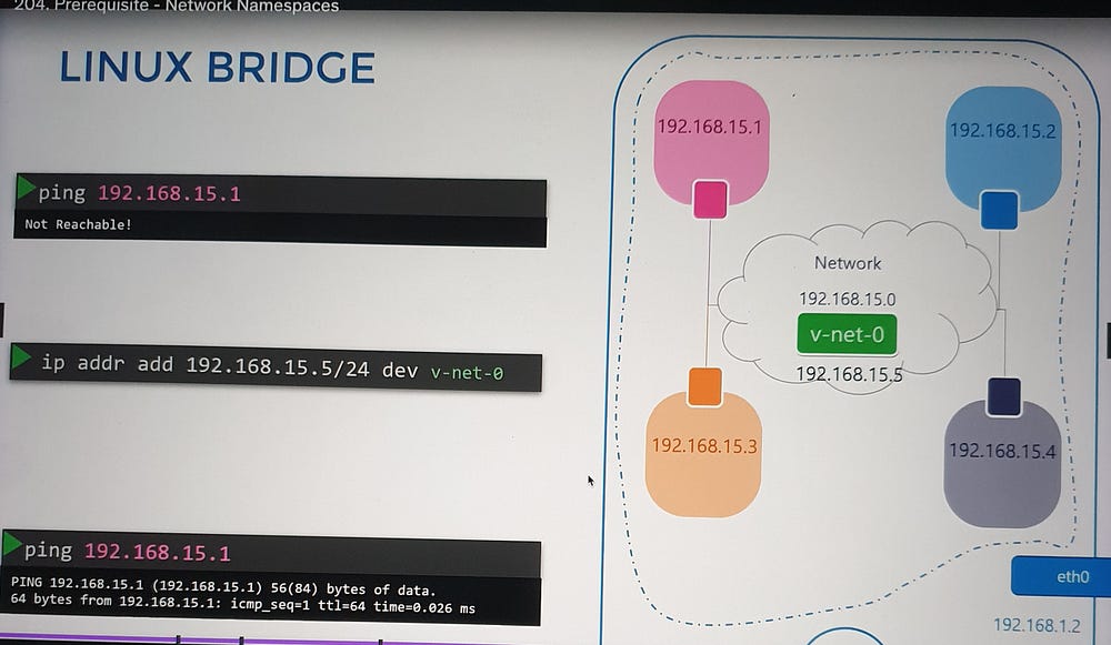
For multiple namespaces, direct connections become cumbersome. A virtual switch, such as a Linux bridge, simplifies this by acting as a central network hub:
Create a bridge:
ip link add [bridge_name] type bridge.Connect namespaces to the bridge: Use virtual Ethernet pairs as before, attaching one end to the namespace and the other to the bridge.
Assign IPs and enable communication: Each namespace gets a unique IP, enabling communication across the virtual network.
External Network Connectivity
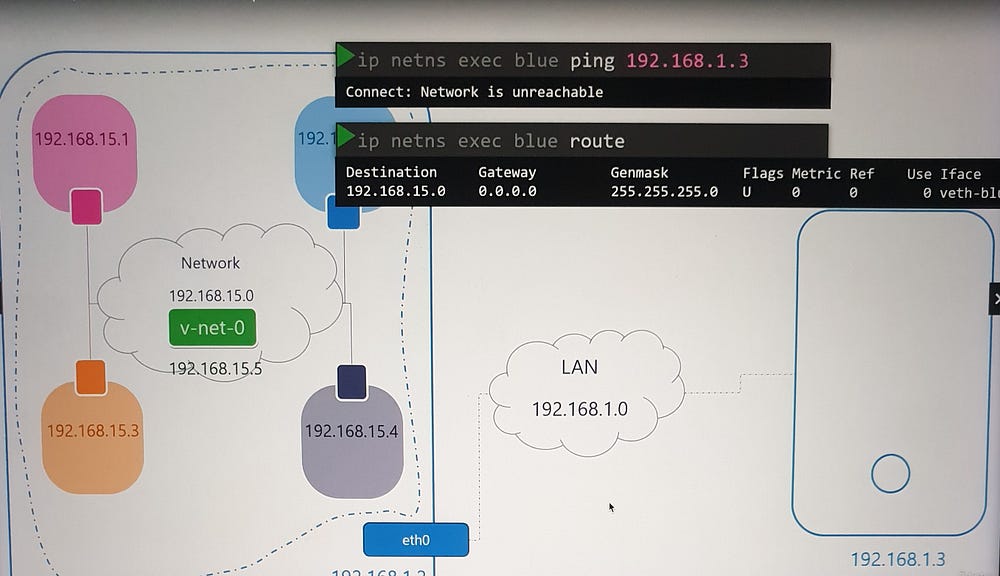
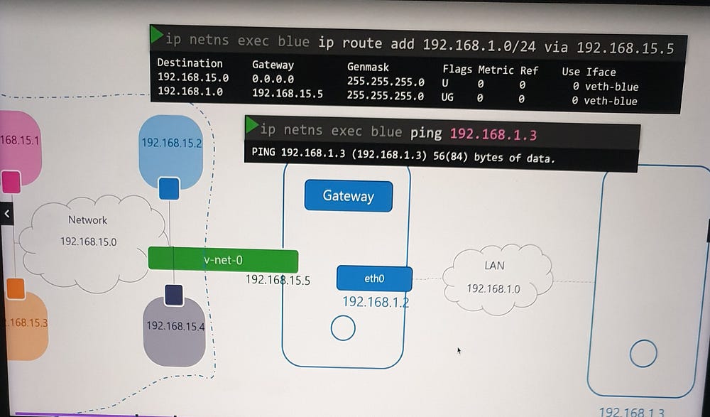
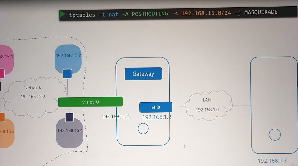
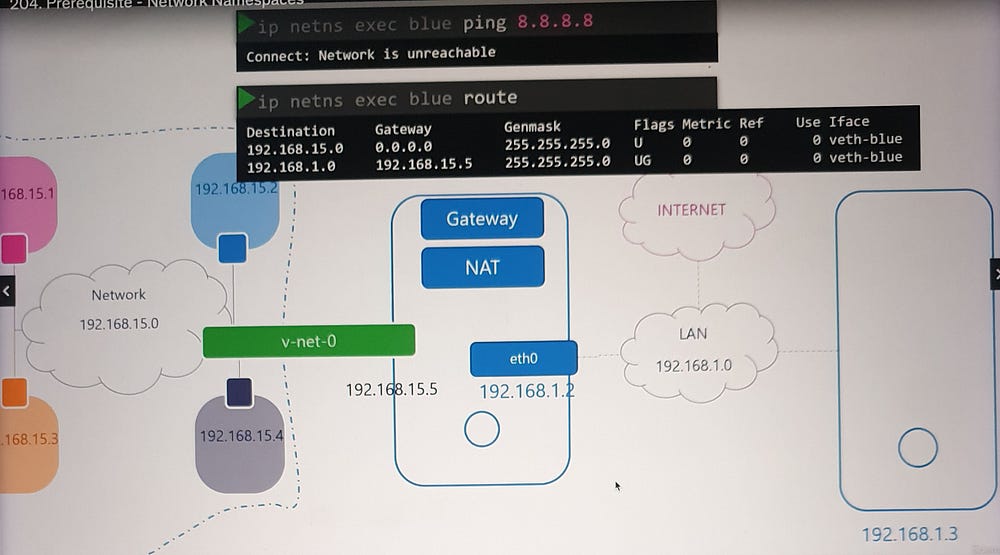
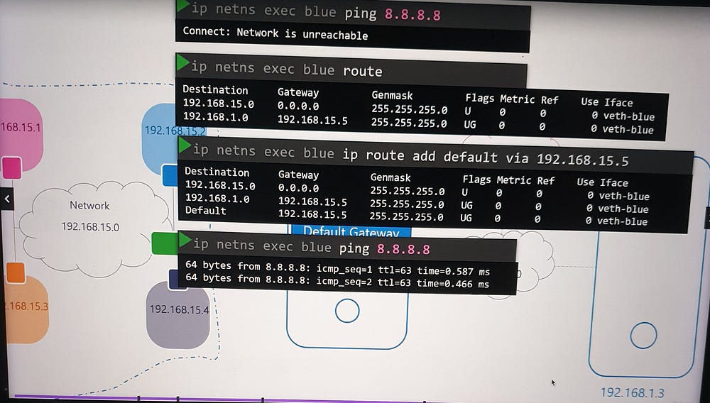
Namespaces are isolated from external networks. To enable external communication:
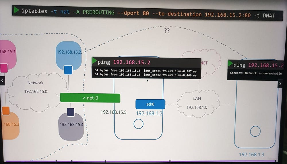
Assign a gateway: Configure a route in the namespace routing table, pointing to the host interface on the bridge network.
Enable NAT: Use
iptablesto masquerade traffic from the namespace network with the host’s external IP.
This allows namespaces to access the internet while maintaining isolation.
Incoming Connectivity
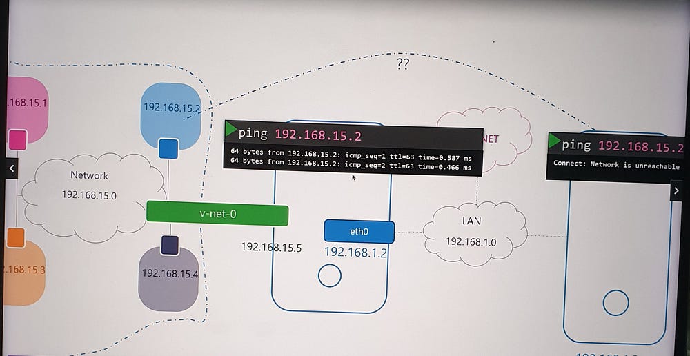
To expose services within a namespace (e.g., a web application on port 80):
Port Forwarding: Use
iptablesto forward traffic from the host's port 80 to the namespace's private IP and port 80.Optional Routing: Alternatively, configure external hosts with a route to the namespace network through the host.
***Docker Networking:
When you run a container, Docker offers various networking options to suit different use cases. Let’s explore these in detail:
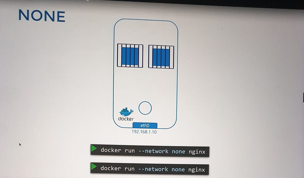
1. None Network
Description: Containers are not attached to any network, ensuring total isolation.
Characteristics:
The container cannot access external networks or be accessed externally.
Multiple containers in this mode cannot communicate with each other.
Use Case: Scenarios where absolute isolation is required, such as debugging or testing.
2. Host Network
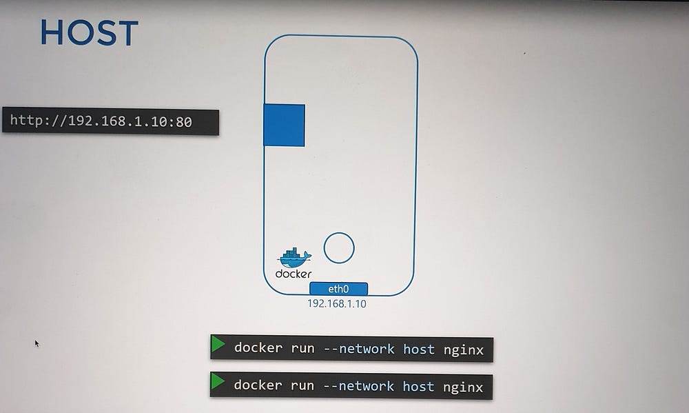
Description: Containers share the host’s network stack.
Characteristics:
No network isolation; the container operates as if running directly on the host.
Applications running in the container are accessible on the same port as the host.
Port conflicts occur if multiple containers try to use the same port.
Use Case: High-performance scenarios where bypassing network virtualization is necessary.
3. Bridge Network (Default)
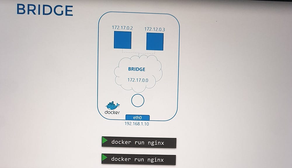
Description: Creates a private internal network connecting the Docker host and its containers.
Characteristics:
Each container gets an IP within the network (e.g.,
172.17.0.0/16by default).Containers can communicate with each other but require port mapping for external access.
Use Case: Standard deployments requiring isolated container communication and selective external exposure.
Bridge Network: A Deeper Dive
The Bridge Network is the default networking mode in Docker, and understanding its mechanics is essential.
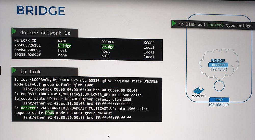
1. Creation and Identification
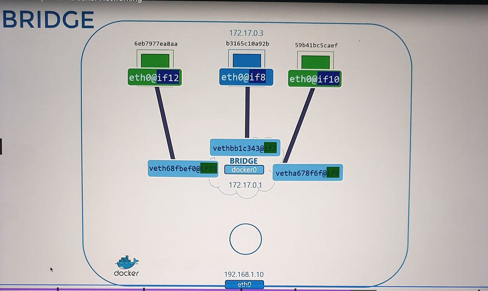
When Docker is installed, it creates an internal bridge network named Bridge (CLI view) or docker0 (host system).
The bridge network is assigned an IP address (e.g.,
172.17.0.1) and acts as:A switch for containers to communicate internally.
An interface for communication with the host.
You can view these networks using:
docker network ls(lists Docker networks).ip link(shows thedocker0interface on the host).
2. Attaching Containers to the Bridge Network
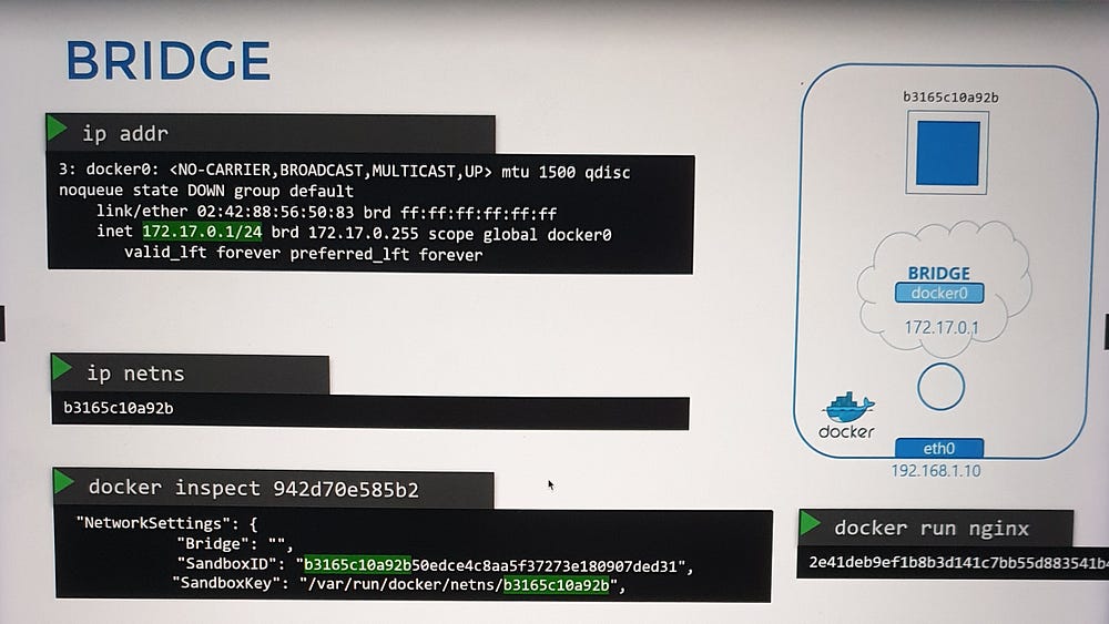
For every container:
Network Namespace Creation: Docker creates a namespace for the container.
Virtual Ethernet Pair:
A virtual cable is created, with one end connected to the container’s namespace and the other to the
docker0bridge.Each interface is assigned an IP address (e.g., container
172.17.0.2).
3. Verification:
Use
ip linkorip addrcommands to inspect interfaces on the host and container.Use
docker inspectto see namespace details.
Interface Pairing and Attachment
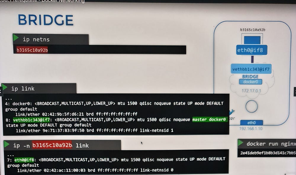
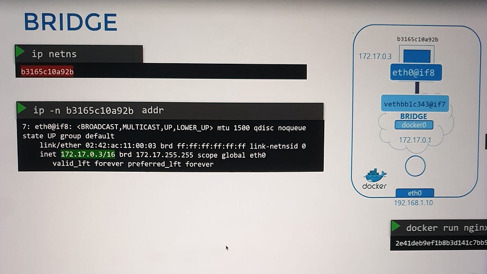
When a container is created:
Namespace Creation: Docker sets up a network namespace for the container.
Virtual Ethernet Pair: A virtual cable with two endpoints is established:
One end connects to the container’s namespace.
The other end connects to the bridge network on the host (
docker0).
3. Numbering System: Interface pairs are identified by their numerical sequence (e.g., 9–10, 11–12).
4. Inter-Container Communication: Once connected, all containers within the same bridge network can communicate directly.
Port Mapping and External Access
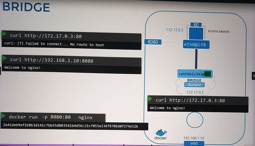
By default, containers in the bridge network are isolated from external access. To enable external communication, port mapping is used.
- Default Scenario:
A container (e.g., running an Nginx web application on port
80) is only accessible:From other containers in the same network.
From the Docker host itself.
External users cannot access the application.
2. Enabling External Access:
Use the port publishing option to map a host port to a container port during container creation.
Example:
-p 8080:80maps port8080on the Docker host to port80in the container.
- Outcome:
External users can access the application using the Docker host’s IP and the mapped port (e.g.,
http://<host-ip>:8080).Traffic to port
8080on the host is forwarded to port80in the container.
Mechanics of Port Forwarding
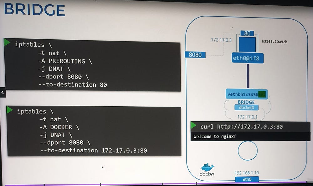
Docker implements port forwarding using NAT (Network Address Translation).
How it Works:
A NAT rule is created in the
iptablesPREROUTING chain, specifying:Source Port: The port on the Docker host (e.g.,
8080).Destination: The container’s IP address and port (e.g.,
172.17.0.3:80).Docker dynamically manages these rules and adds them to the Docker-specific chain in
iptables.
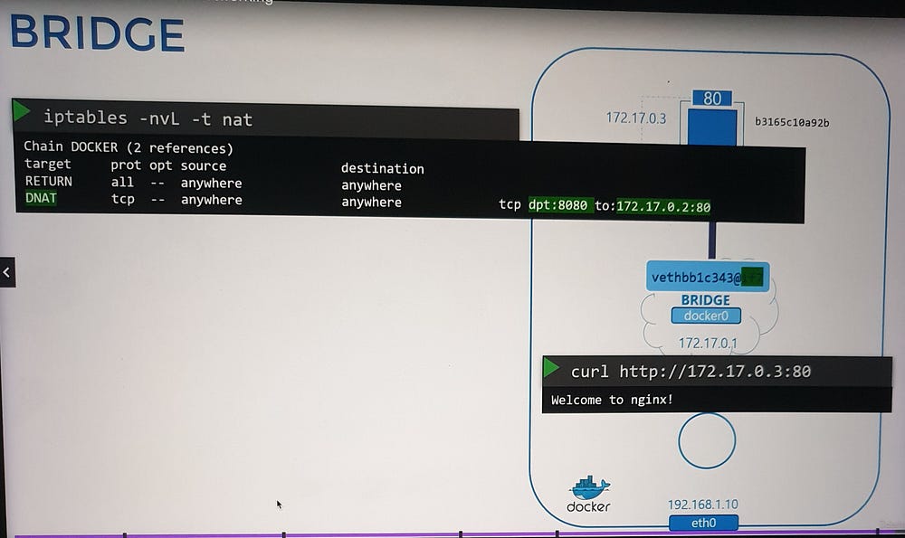
Verification:
- Use
iptablescommands to view and inspect the rules Docker creates.
***Container Networking Interface(CNI)
Understanding CNI
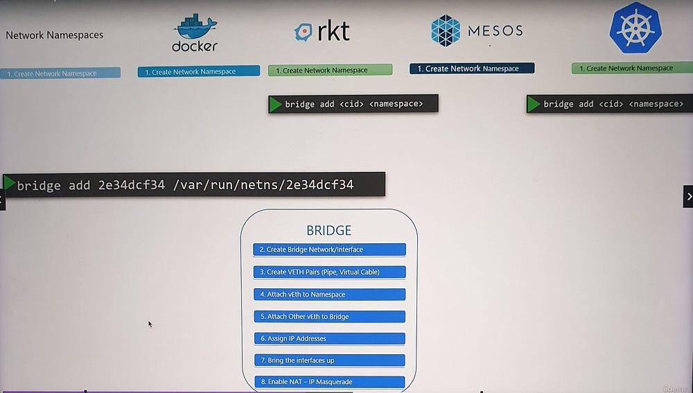
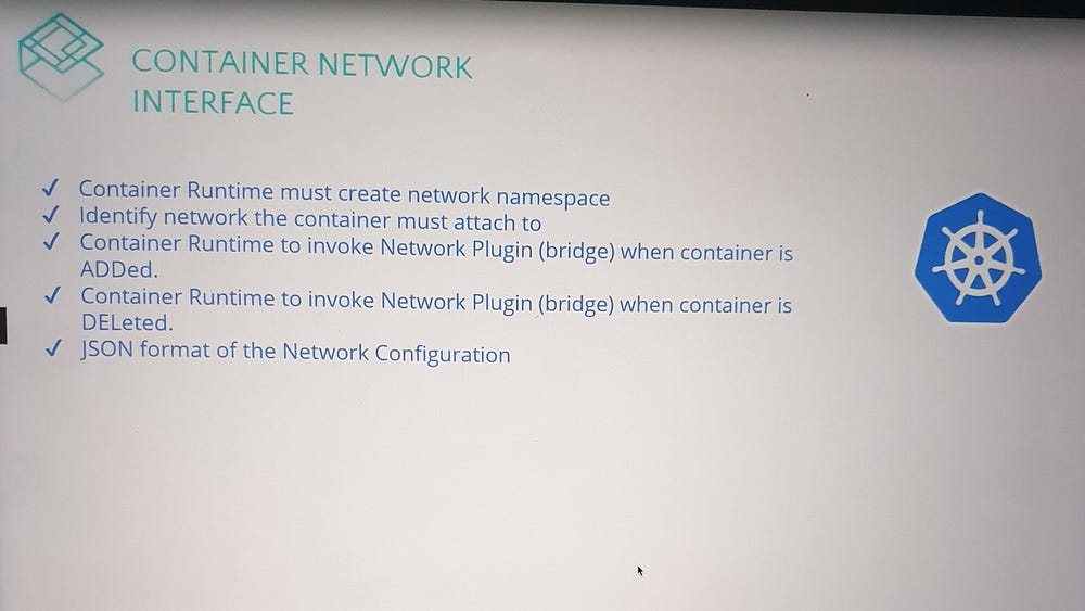
The Container Networking Interface (CNI) defines a set of standards for creating networking plugins and integrating them with container runtimes.
Plugins: Programs that handle container networking (e.g., connecting a container to a network).
Bridge Plugin Example: A plugin named
Bridgeperforms tasks such as assigning IPs, attaching containers to namespaces, and managing routing.
CNI’s Responsibilities
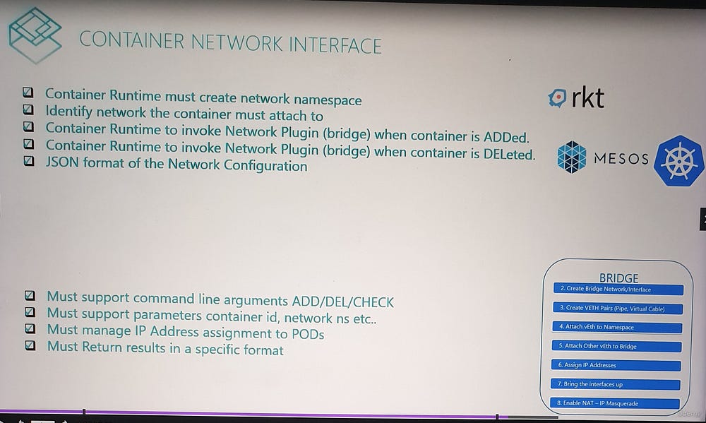
- For Container Runtimes:
Create a network namespace for each container.
Identify the networks to which a container should connect.
Invoke the plugin when a container is created or deleted, using:
ADDcommand (on container creation).DELcommand (on container deletion).Configure plugins using a JSON file.
2. For Plugins:
- Support commands like
ADD,DEL, andCHECK, which accept parameters such as container ID and network namespace.
Handle tasks such as:
Assigning IP addresses to containers.
Configuring routes to enable communication between containers.
Return results in a standardized format.
As long as both runtimes and plugins adhere to these standards, they work seamlessly together, ensuring compatibility across platforms.
Built-In Plugins and Third-Party Integrations
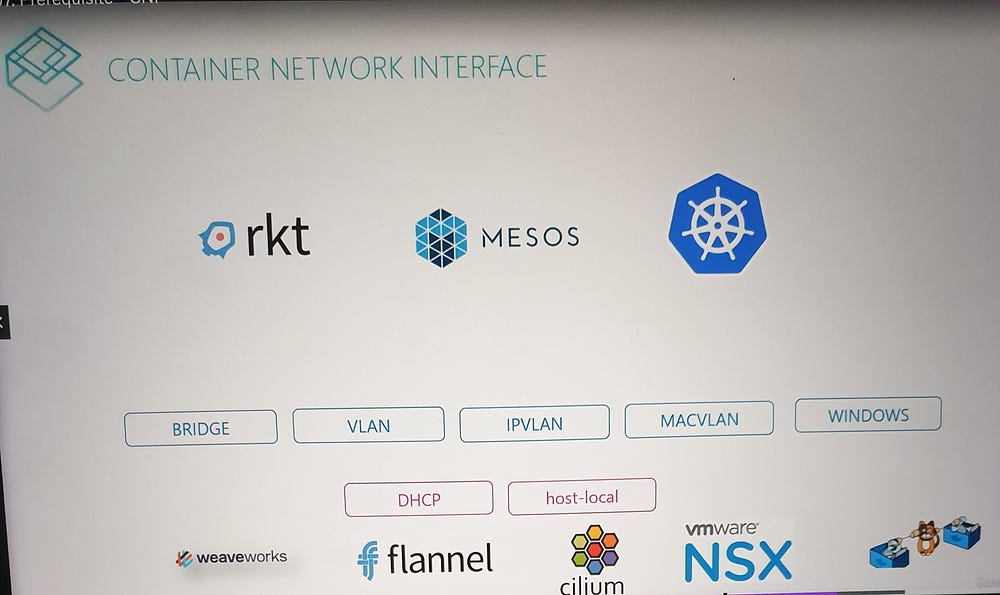
CNI includes several prebuilt plugins, such as:
Bridge
VLAN, IP VLAN, MAC VLAN
Windows-specific plugins
IPAM Plugins like Host Local and DHCP
Additionally, third-party plugins, such as Weave, Flannel, Calico, Cilium, and VMware NSX, implement the CNI standard, enabling diverse networking capabilities.
CNI vs. Docker’s CNM
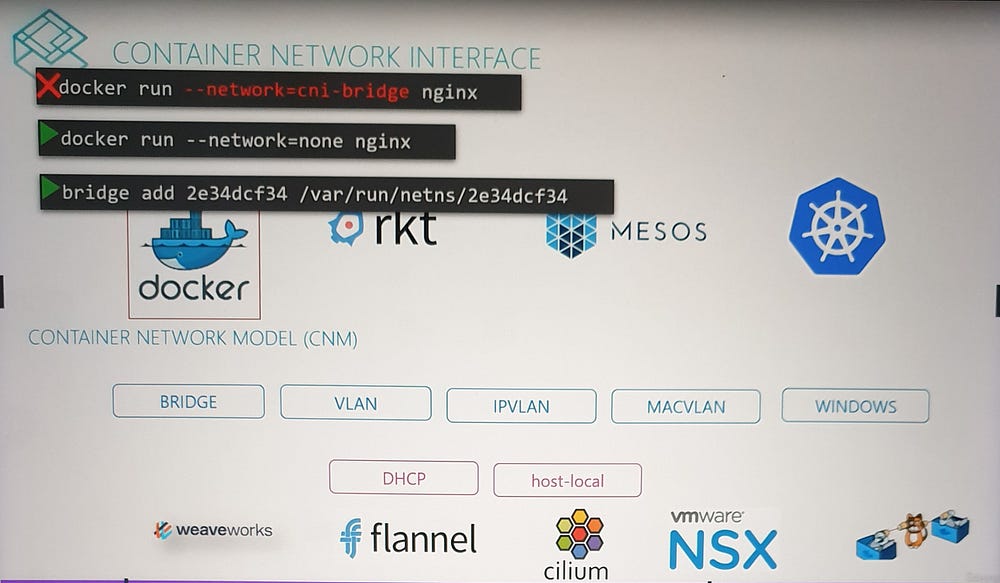
While many container runtimes (e.g., Kubernetes, Mesos) adopt the CNI standard, Docker uses its own networking model, the Container Network Model (CNM).
Differences:
CNM provides an alternative approach to container networking, making Docker incompatible with CNI plugins by default.
As a result, Docker containers cannot natively use CNI plugins.
Workaround:
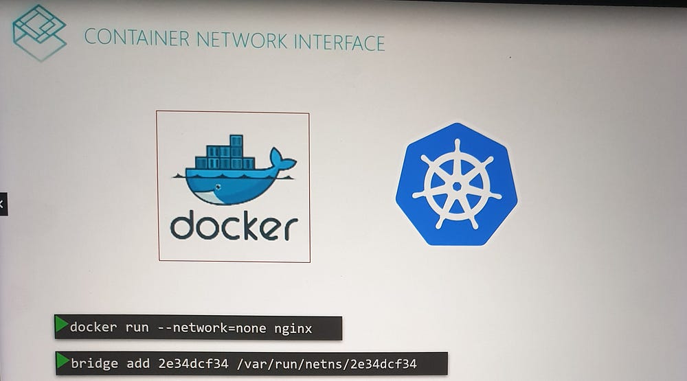
Create a Docker container with no network configuration.
Manually invoke the desired CNI plugin (e.g.,
Bridge).
This is precisely how Kubernetes interacts with Docker:
Kubernetes creates containers with no network (
none).Configured CNI plugins handle the rest of the networking setup.
***Cluster Networking
Basic Networking Requirements
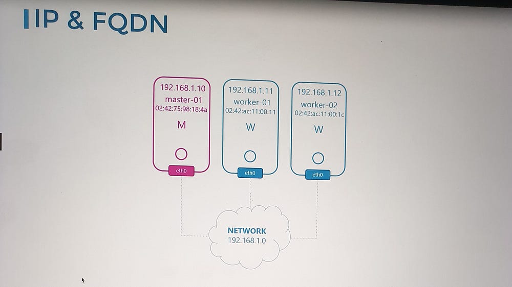
A Kubernetes cluster consists of master and worker nodes, and each node must meet the following criteria:
- Network Interface:
Each node should have at least one network interface connected to a network.
The interface must have a unique IP address.
2. Host Identity:
Each node must have:
A unique hostname.
A unique MAC address for its network interface
Important: If you created the nodes by cloning existing virtual machines, ensure these identifiers are updated to avoid conflicts.
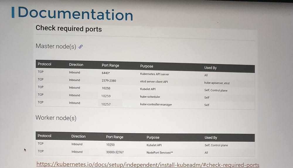
Required Open Ports
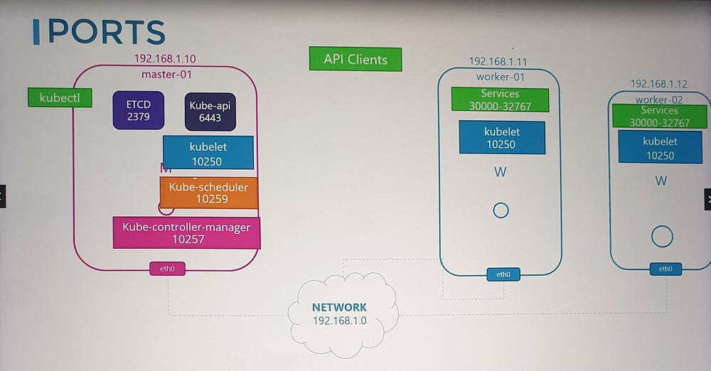
To facilitate communication between Kubernetes components, certain ports need to be open:
- API Server (Port 6443):
The master node’s API server listens on this port.
Used by:
Worker nodes.
kubectltool.External users.
Other control plane components.
2. Kubelet (Port 10250):
Kubelet agents on both master and worker nodes listen on this port.
Note: The master node may also run a kubelet.
3. Scheduler (Port 10259):
- The kube-scheduler component requires this port to be open.
4. Controller Manager (Port 10257):
- The kube-controller-manager requires this port for communication.
5. Worker Node Service Ports (30000–32767):
- These ports are used to expose services on worker nodes for external access.
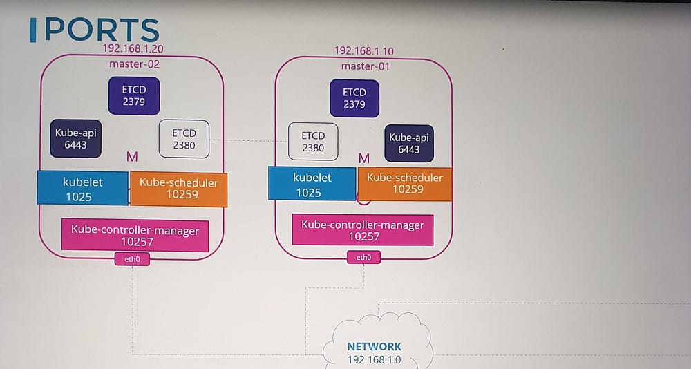
6. ETCD Server Ports:
Port 2379: Used by ETCD server to listen for incoming requests.
Port 2380: Required for communication between ETCD instances in multi-master configurations.
Considerations for Multi-Master Clusters
If you have multiple master nodes, ensure all the ports listed above are open on every master node. This is especially important for ETCD communication (port 2380).
Network Security Configurations
When configuring networking for your Kubernetes cluster, keep these considerations in mind:
Firewall Rules: Ensure the necessary ports are allowed through firewalls.
IP Tables Rules: Review and configure rules to permit communication between nodes.
Cloud Security Groups: If deploying on platforms like AWS, Azure, or GCP, adjust the network security groups accordingly.
If something is not working as expected, checking these configurations is a good starting point during troubleshooting.
***Pod Networking
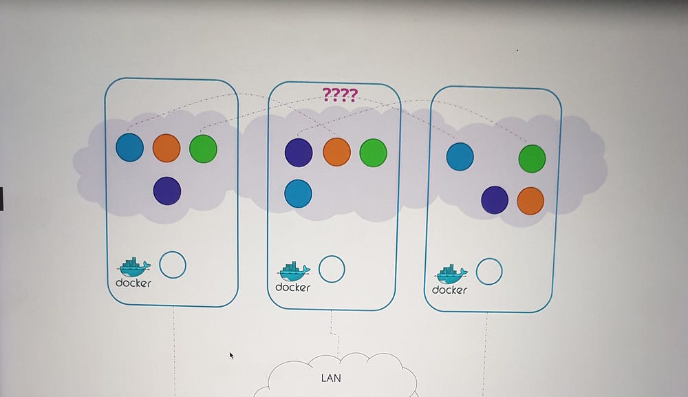
Understanding the Need for Pod Networking
In Kubernetes, the network setup that connects nodes together is distinct from the networking required for pods. As the cluster grows to accommodate numerous pods and services, key questions arise:
How are pods addressed?
How do they communicate with each other?
How can services running on these pods be accessed, both internally and externally?
Kubernetes does not provide a built-in solution for these challenges. Instead, it expects users to implement a networking model that meets specific requirements.
Kubernetes Pod Networking Requirements
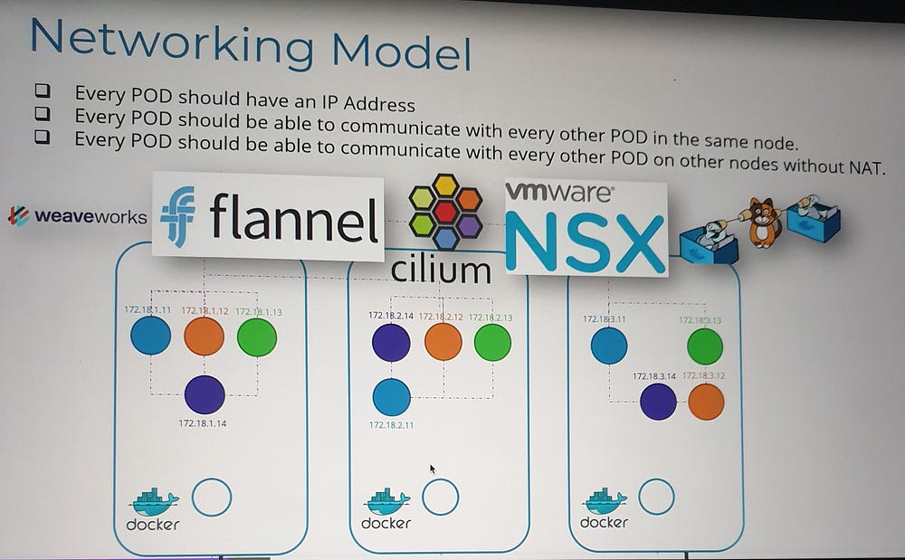
Kubernetes defines the following expectations for pod networking:
Unique Pod IPs: Every pod must have a unique IP address.
Intra-Node Communication: Pods within the same node should be able to communicate using their IP addresses.
Inter-Node Communication: Pods on different nodes must also communicate seamlessly using the same IP addresses, without requiring Network Address Translation (NAT).
The specifics of IP ranges and subnets are left to the implementer, provided these criteria are satisfied.

Implementing Pod Networking
While there are several solutions available to address these requirements, such as Container Network Interface (CNI) plugins, understanding the fundamentals helps in grasping how these solutions work.
Setting the Foundation
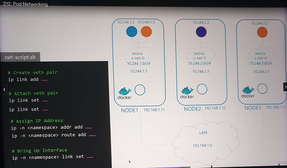
Let’s begin with a three-node cluster where each node has an external IP address (e.g., 192.168.1.11, 192.168.1.12, 192.168.1.13). The nodes participate in a common network, and Kubernetes creates network namespaces for containers (pods) upon their creation. To facilitate communication, we:
Create a Bridge Network: A bridge network is established on each node to interconnect the containers.
Assign IP Subnets: Each node’s bridge network is assigned a unique subnet (e.g., 10.240.1.0/24 for Node 1, 10.240.2.0/24 for Node 2, etc.).
Connecting Containers
When a container is created:
A virtual network cable (veth pair) is generated using
ip link add.One end is attached to the container, and the other to the bridge using
ip link set.An IP address is assigned to the container using
ip addr.A default route is configured to the bridge network’s gateway.
This process is repeated for each container, enabling them to communicate within the same node.
f
Inter-Node Communication
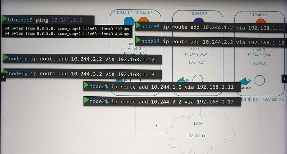
To enable communication between nodes:
- Routes are added to each node’s routing table, directing traffic to the appropriate subnet of other nodes. For example:
- Node 1 routes traffic to 10.240.2.0/24 via Node 2’s external IP (192.168.1.12).
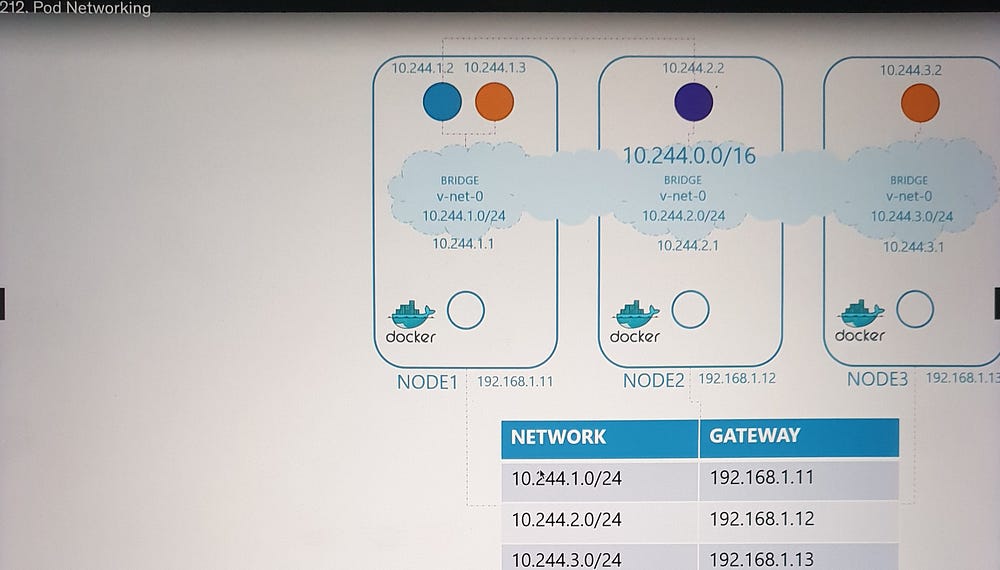
- Alternatively, a central router can manage these routes, simplifying configuration as the network grows.
Unified Network Architecture
The individual bridge networks now form a single logical network (e.g., 10.244.0.0/16), enabling seamless pod-to-pod communication across nodes.
Automation with CNI
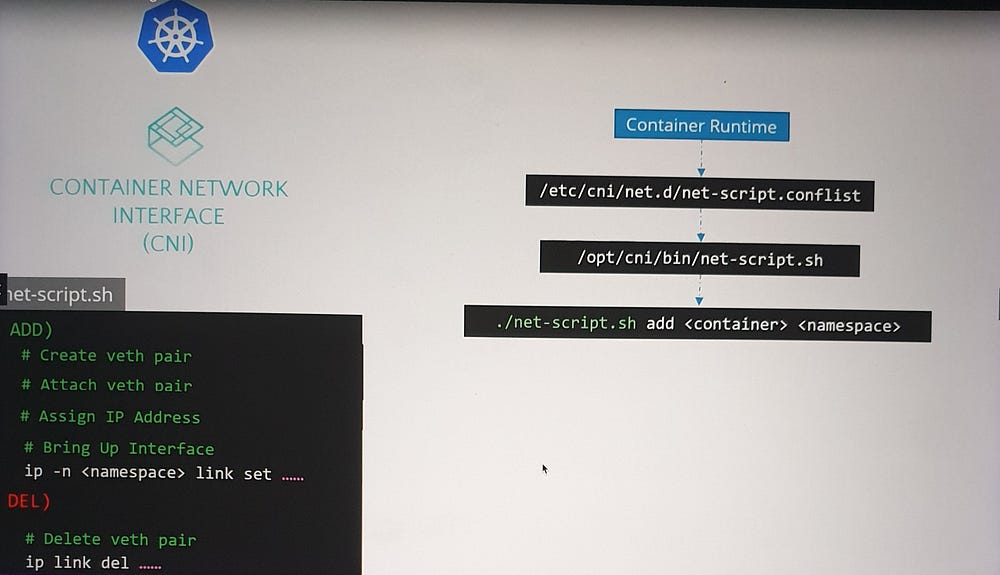
Manual configuration of pod networking is impractical for large-scale environments. This is where CNI (Container Network Interface) comes into play.
CNI Overview:
CNI provides a standard framework for networking containers.
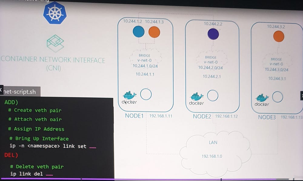
It ensures that when a pod is created, a pre-defined script is executed to handle network setup.
Script Adaptation:
The script must adhere to CNI standards, including:
An add section for connecting containers to the network.
A delete section for cleaning up resources when containers are removed.
When a container is created, the container runtime (e.g., Docker, CRI-O) uses the CNI configuration to locate and execute the script, automating the networking process.
***Container Networking Interface(CNI) in Kubernetes:
CNI Responsibilities in Kubernetes
CNI defines the responsibilities of the container runtime. For Kubernetes, this means:
Creating container network namespaces.
Attaching these namespaces to the appropriate networks by invoking the specified CNI plugin.
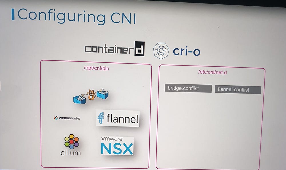
The container runtime, such as Containerd or CRI-O, is the Kubernetes component responsible for creating containers and triggering the appropriate network plugin after a container is created.
Configuring Kubernetes to Use CNI Plugins
CNI Plugin Installation
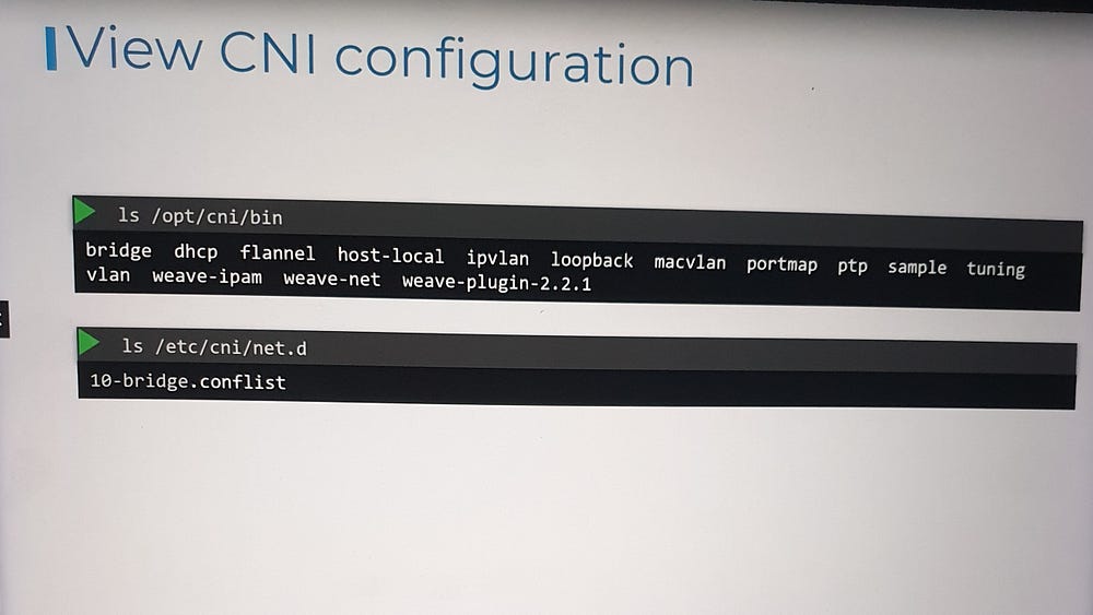
- Plugin Directory:
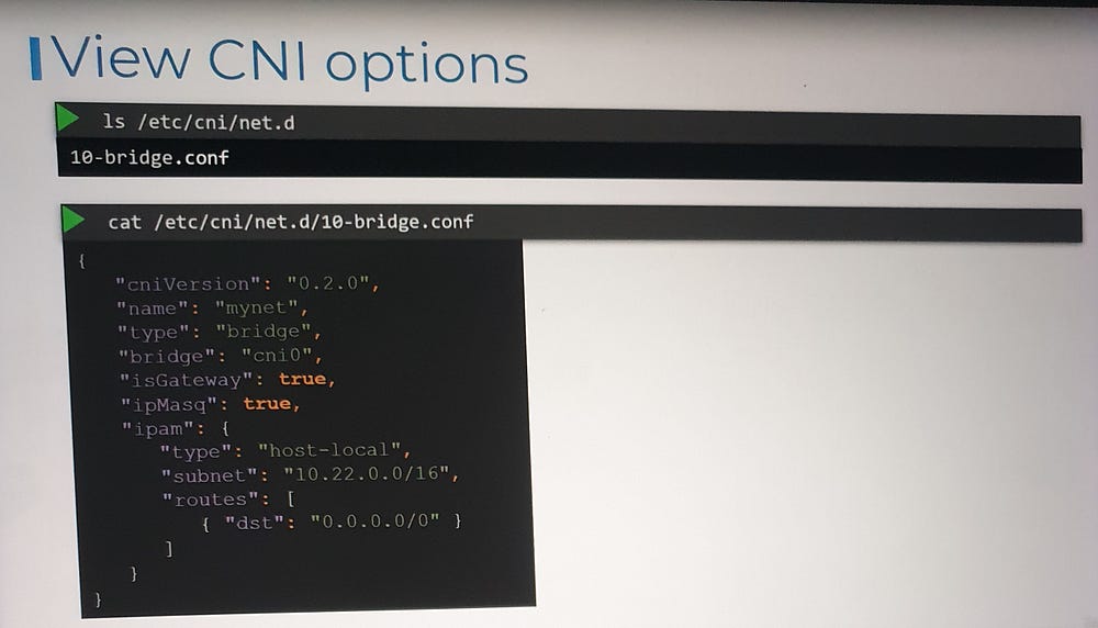
All network plugins are installed in
/opt/cni/bin.This directory contains executable files for each plugin, such as
bridge,flannel,dhcp, etc.
2. Configuration Files:
Plugin configurations are stored in
/etc/cni/net.d.Each file defines how a specific plugin should be used.
If multiple configuration files exist, the container runtime selects the one with the alphabetically first name.
Key Elements:
name: The name of the network (e.g., "mynet").type: The plugin type (e.g., "bridge").isGateway: Determines whether the bridge interface gets an IP address to act as a gateway.ipMasq: Enables NAT rules for IP masquerading.ipam: Handles IP address management.type: Indicates whether IPs are managed locally (host-local) or by an external DHCP server.subnet: Defines the IP address range for the network.
This configuration ties together concepts like bridging, routing, NAT, and IP allocation, which were covered in earlier lectures.
Key Takeaways
Kubernetes relies on the container runtime (e.g., Containerd, CRI-O) to invoke CNI plugins and manage pod networking.
CNI plugins and their configurations are managed through standard directories:
Executables:
/opt/cni/binConfigurations:
/etc/cni/net.d
3. The CNI configuration file defines the network type, IP allocation, routing rules, and NAT behavior.
***Understanding Weaveworks Weave CNI Plugin in Kubernetes
Challenges of Scaling Pod Networking
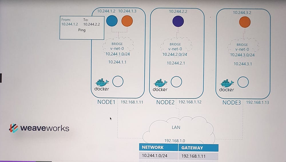
In the basic networking solution we built earlier, a routing table mapped networks across nodes. When a packet was sent between pods on different nodes, it traversed the network using this routing table. While this approach works in small, simple environments, it becomes impractical as the scale increases.
Scaling Limitations
Routing Table Size: Managing a large number of routes becomes inefficient as clusters grow to hundreds of nodes with thousands of pods.
Complexity: Maintaining accurate routing tables in large, dynamic environments is challenging.
Analogy: Scaling Office Communication
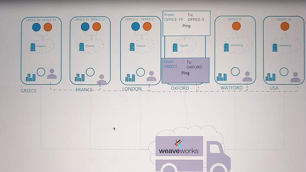
To simplify the concept, imagine the Kubernetes cluster as a company, where:
Nodes are different office sites.
Pods are departments or offices within each site.
Initially, employees (pods) sent packages directly to other offices using local couriers, relying on addresses and direct routes. As the company expanded globally, this approach failed due to logistical complexities.
Solution: A professional shipping company was engaged to streamline communication:
Agents: Representatives were placed at each site to manage shipments.
Coordination: Agents communicated to share information about all sites, departments, and offices.
Encapsulation: Packages were re-wrapped for efficient transport between sites.
Delivery: Agents ensured packages reached the correct department upon arrival.
How Weaveworks Solves Networking Challenges
Weaveworks employs a similar model:
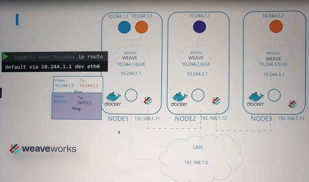
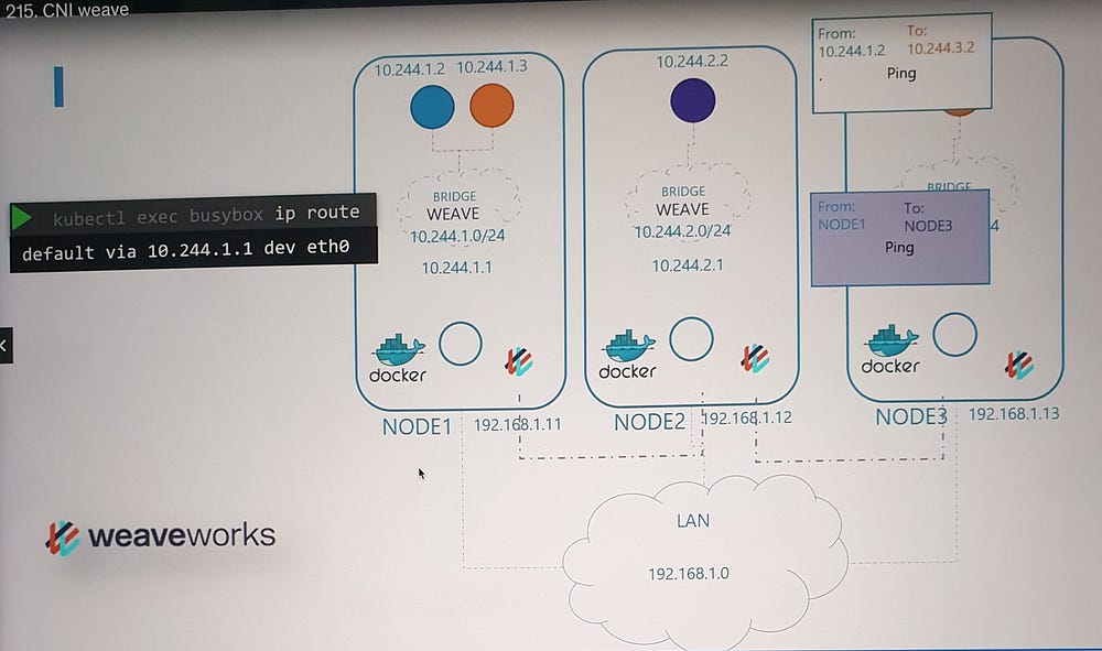
Weave Agents: A Weave agent (or peer) is deployed on each Kubernetes node. These agents exchange information about nodes, networks, and pods to maintain a complete topology of the cluster.
Bridge Network:
Weave creates a bridge network named weave on each node.
IP addresses are assigned to the network and its pods dynamically.
Packet Flow in Weave
Source Node: When a packet is sent from a pod, Weave intercepts it and identifies the destination pod.
Encapsulation:
The packet is encapsulated into a new one with updated source and destination information.
Transmission: The encapsulated packet is sent across the network to the destination node.
Destination Node:
The Weave agent on the receiving node decapsulates the packet and forwards it to the correct pod.
This approach removes the need for extensive routing tables, ensuring efficient and scalable communication in large clusters.
Weave Deployment in Kubernetes
Deployment Methods
- Manual Deployment:
- Weave agents can be installed as standalone services or daemons on each node.
2. Kubernetes Integration:
- The preferred method is deploying Weave as pods in the Kubernetes cluster using DaemonSets.
Why DaemonSets?
A DaemonSet ensures that a specific pod type is deployed on all nodes in the cluster. For Weave, this guarantees that each node runs a Weave agent, facilitating seamless communication.
Deployment Process
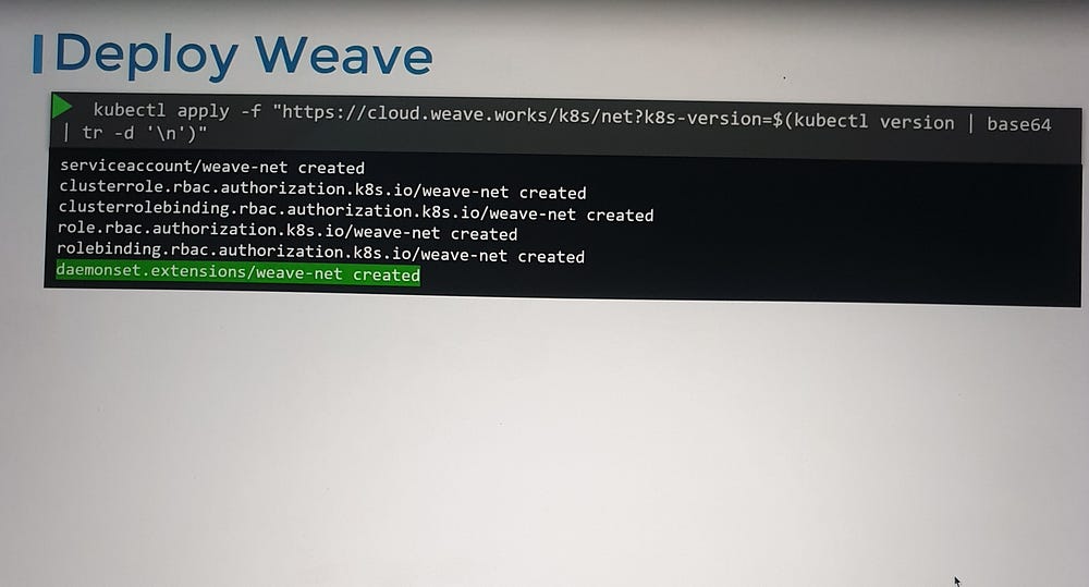
With a kubectl apply command, Weave can be deployed in a running Kubernetes cluster.
This command sets up:
Weave agents (peers) as a DaemonSet.
Additional components necessary for the plugin’s functionality.
Post-Deployment Observation
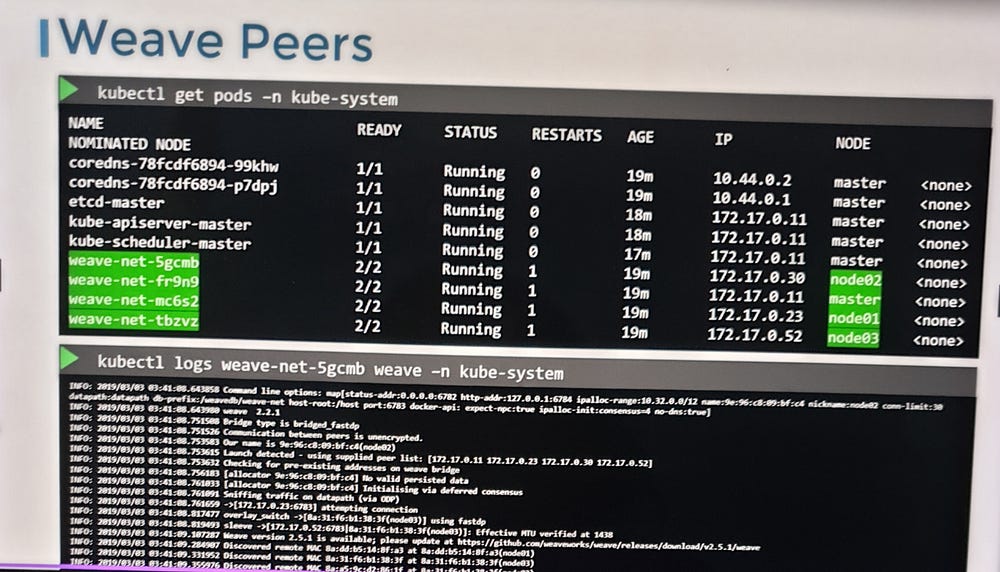
If your cluster is set up using tools like kubeadm, you can verify the Weave installation:
Use
kubectl get pods -n kube-systemto list the Weave pods.Each node will have a Weave pod deployed.
Troubleshooting Weave
For debugging:
Use
kubectl logsto check logs from Weave pods.Investigate the configuration files and IP address allocation to identify potential issues.
***IP Address Management- Weave
Who Manages IP Address Allocation?
As per the Container Network Interface (CNI) standards, the responsibility for managing IP address assignment lies with the CNI plugin or the network solution provider.
IP Management in a Basic CNI Plugin
Previously, we implemented a custom CNI plugin, where we directly handled the assignment of IP addresses within the plugin itself. This included managing the allocation of IPs to container network namespaces.
While Kubernetes itself doesn’t dictate how IPs should be assigned, it mandates:
No duplicate IPs across the network.
Proper management of IP allocations.
Approaches to IP Address Management
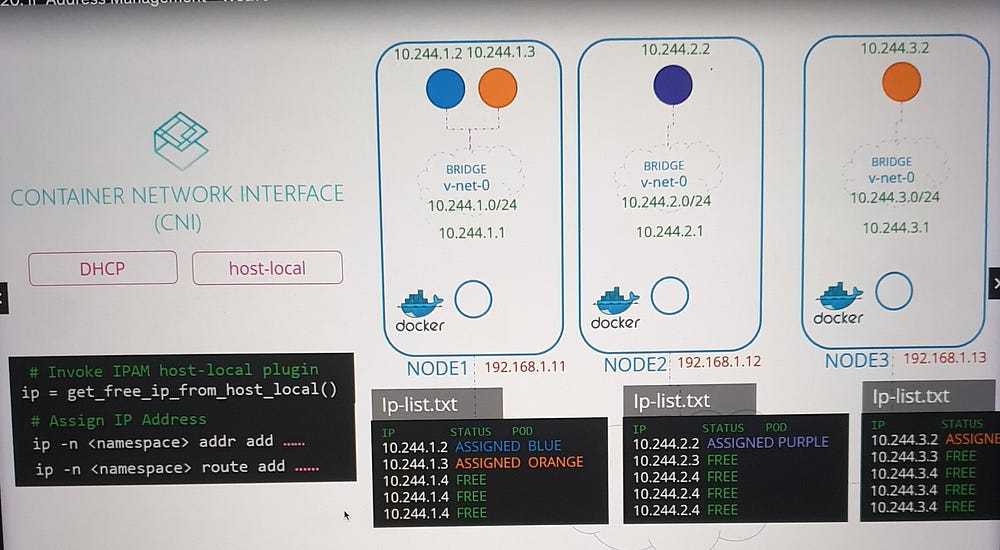
Local File-Based Management
A straightforward method to manage IPs is to:
Maintain a list of allocated IP addresses in a file stored locally on each host.
Include logic in the CNI plugin script to read, update, and validate entries in this file.
CNI’s Built-in Plugins
Instead of implementing manual logic, CNI provides built-in IPAM plugins to handle this task.
- Host-Local Plugin:
Assigns IPs locally on each host, ensuring no overlap.
Requires the CNI plugin script to invoke it explicitly.
2. Dynamic Configuration:
CNI configuration files contain an
IPAMsection specifying the type of plugin, subnet, and routes to be used.A dynamic script can read these configurations and invoke the appropriate plugin.
Integration with Network Providers
Each network solution provider has its unique method of managing IPs. For example, let’s look at how Weave works Weave handles this process.
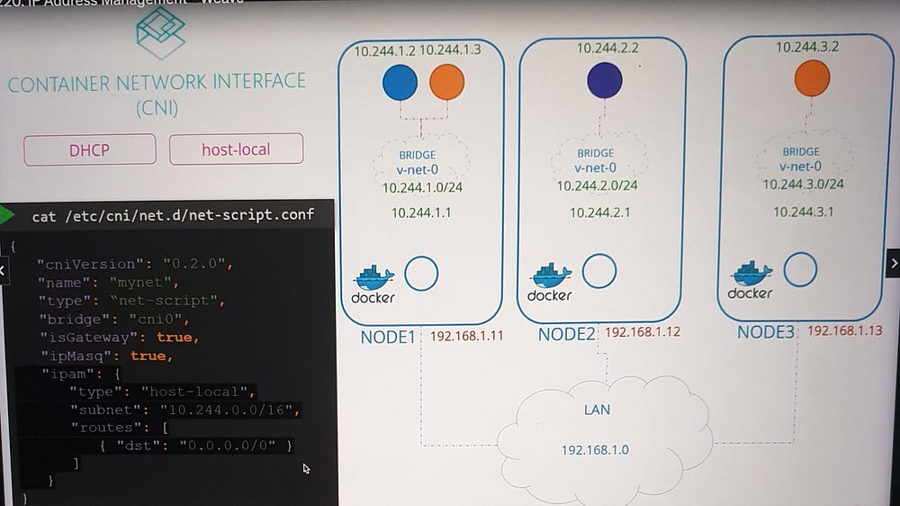
Weave works Weave IP Address Management
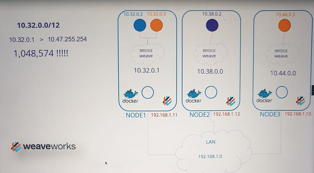
Weave uses an efficient and scalable approach to IP allocation:
- Default IP Range:
- By default, Weave allocates the range 10.32.0.0/12 to the cluster. This provides approximately one million usable IPs, from 10.32.0.1 to 10.47.255.254, for pod networking.
2. IP Range Distribution:
Weave peers (agents) on each node split the IP range equally among themselves.
Each node is assigned a subset of the IP range for use by its pods.
3. Configuration Options:
- The default range is configurable. Additional parameters can be specified during the deployment of the Weave plugin, allowing customization based on the cluster’s requirements.
Key Takeaways
CNI Plugins are responsible for IP allocation and management.
Kubernetes does not enforce specific methods but requires unique IPs across the cluster.
Weave uses a distributed approach for efficient IP range allocation, making it scalable for large clusters.
IPAM configurations can be customized through CNI configuration files and dynamic scripting.
***Understanding Service Networking in Kubernetes:
What are Services?
A service is an abstraction that provides a stable network endpoint to access applications running in pods.
Each service is assigned:
A unique IP address.
A name (for DNS-based access).
Types of Services
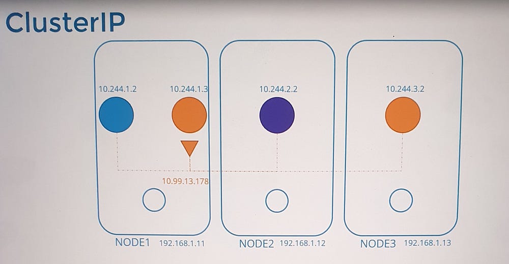
- Cluster IP (Default):
Makes the service accessible only within the cluster.
Ideal for internal applications like databases.
2. Node Port:
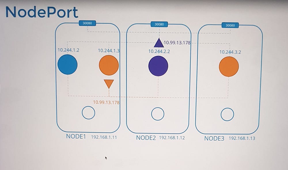
Extends accessibility outside the cluster by exposing the service on a specific port of all nodes.
Useful for external-facing applications.
How Services Work in Kubernetes
Cluster-Wide Accessibility
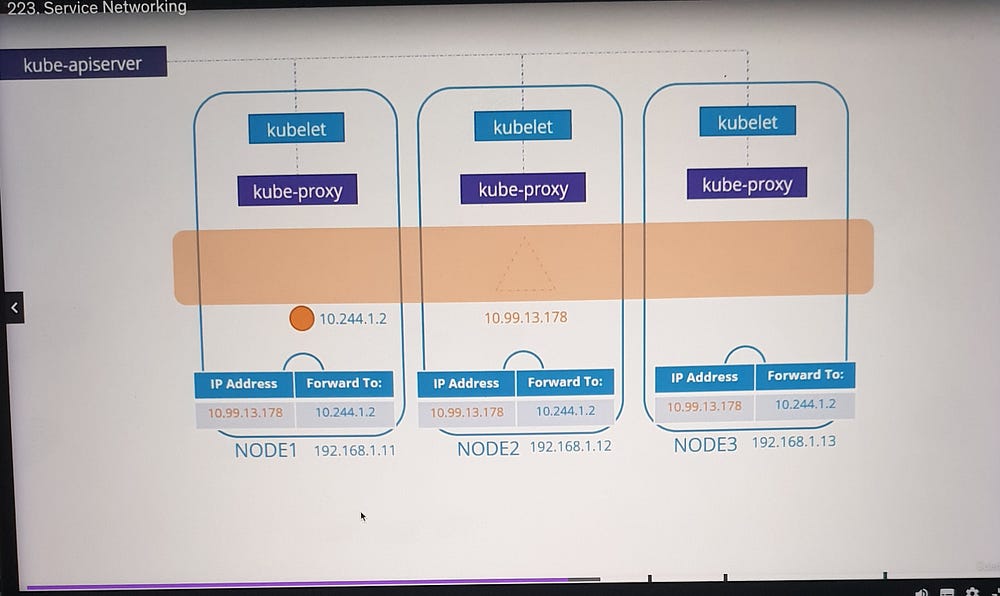
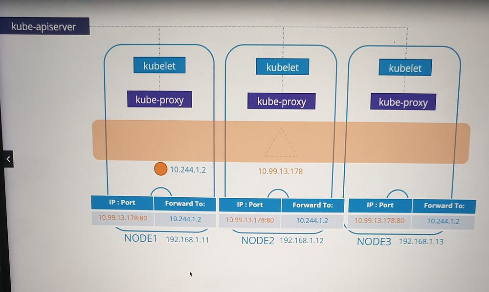
Unlike pods, which are tied to specific nodes, services exist across the cluster. They are:
Virtual objects, meaning they do not involve actual processes, namespaces, or interfaces.
Managed entirely by Kubernetes components such as kube-proxy.
Service IP Address Assignment
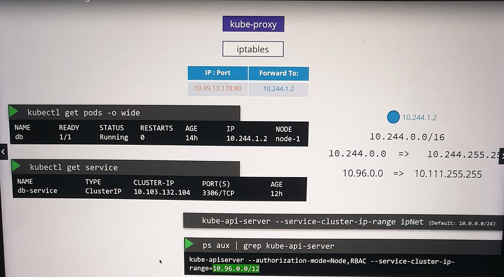
Kubernetes assigns service IPs from a predefined range specified by the
--service-cluster-ip-rangeflag in the API server.Example:
Service CIDR:
10.96.0.0/12Pod CIDR:
10.244.0.0/16The ranges must not overlap to avoid conflicts between pod and service IPs.
Role of kube-proxy
The kube-proxy component:
Runs on every node.
Monitors the Kubernetes API server for service-related events.
Configures the network to route traffic to the appropriate pod(s).
How kube-proxy Operates
- When a service is created, kube-proxy:
Retrieves the service’s assigned IP address and port.
Sets up forwarding rules on each node to map service IP traffic to pod IPs.
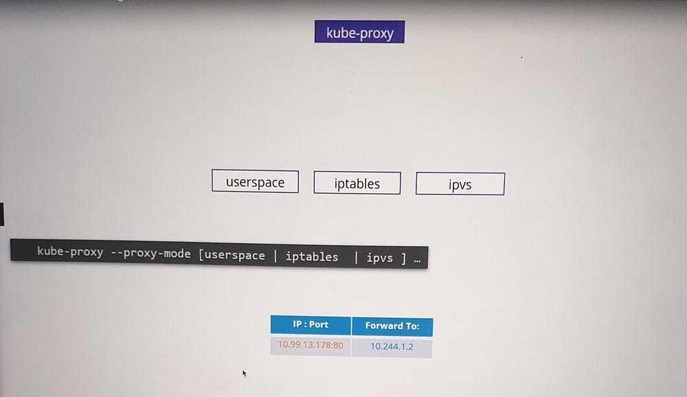
2. Supported Modes:
iptables (Default): Uses NAT rules to redirect traffic to backend pods.
IPVS: Implements a scalable, performance-optimized load balancer.
User space: Legacy mode, listens on service ports and proxies requests to pods.
The default mode is iptables, but it can be customized using the --proxy-mode option.
Example: Cluster IP Service
Scenario
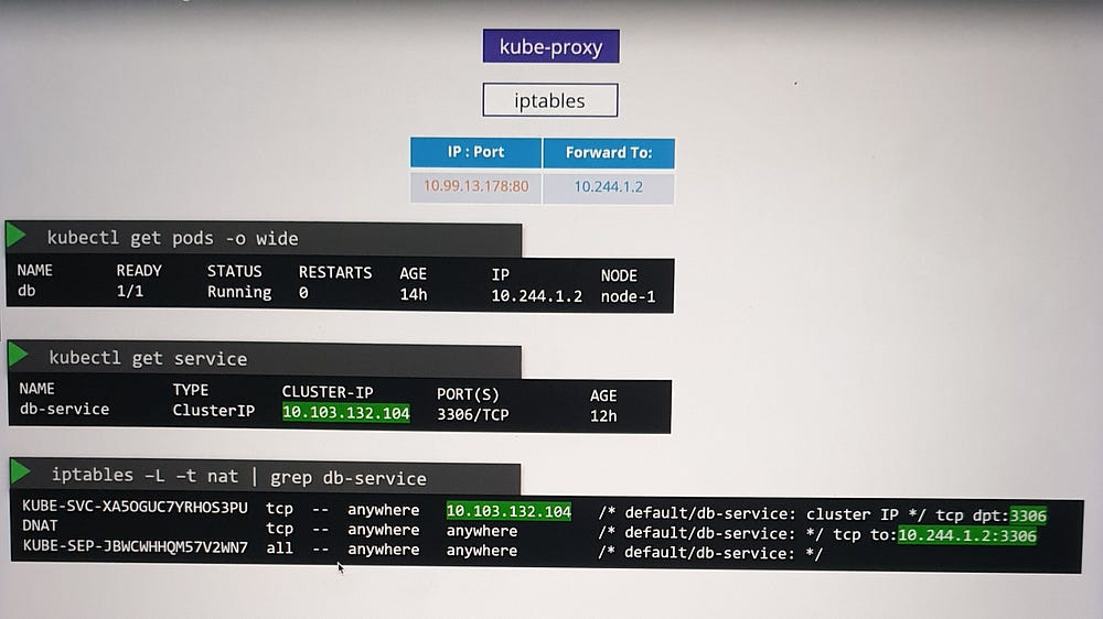
A pod named
dbruns on Node 1 with IP10.244.1.2and exposes a database on port 3306.A ClusterIP service is created to make this pod accessible within the cluster.
Process
Kubernetes assigns the service an IP, e.g.,
10.103.132.104.kube-proxy adds DNAT rules to iptables:
- Incoming traffic to the service IP
10.103.132.104:3306is redirected to the pod IP10.244.1.2:3306.
Verification
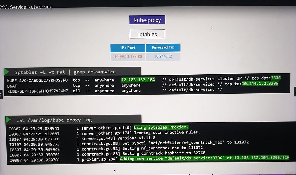
Use
iptablesto view NAT table entries.Rules created by kube-proxy include comments with the service name for easy identification.
Example: NodePort Service
Scenario
A web application is hosted on a pod and requires external access.
A NodePort service is created, exposing the application on a specific port across all nodes.
Process
kube-proxy sets up iptables rules to forward traffic from the node’s port to the pod’s IP and port.
External users access the application using the
<NodeIP>:<NodePort>combination.
Logging and Troubleshooting
To troubleshoot kube-proxy configurations:
- Check the kube-proxy logs for details about:
Proxy mode in use (e.g., iptables, IPVS).
Service creation or deletion events.
2. Ensure appropriate log verbosity levels for detailed insights.
Key Considerations
Separate CIDR Ranges: Ensure the service and pod CIDR ranges do not overlap.
Dynamic Updates: kube-proxy dynamically updates iptables rules when services are added or removed.
Virtual Nature: Services are purely conceptual, relying on forwarding rules for functionality.
***Cluster DNS
DNS in Kubernetes Clusters:
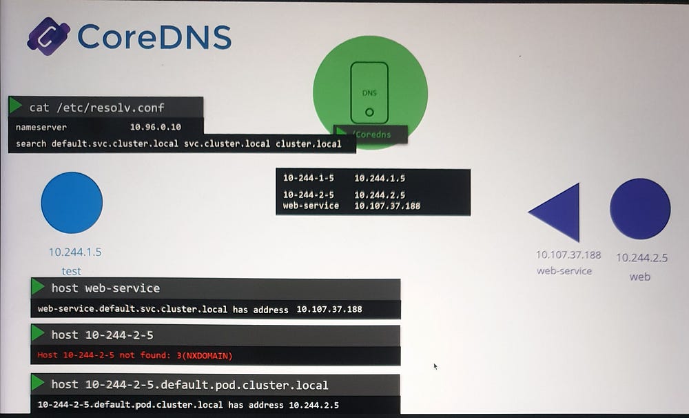
Kubernetes deploys a built-in DNS server (usually Core DNS) by default. This server is responsible for managing name resolution within the cluster, enabling seamless communication between components like pods and services.
Key Points:
All pods and services have unique IP addresses.
The cluster networking is correctly configured.
DNS primarily focuses on pods and services; nodes and their external DNS configuration are outside the scope of this lecture.
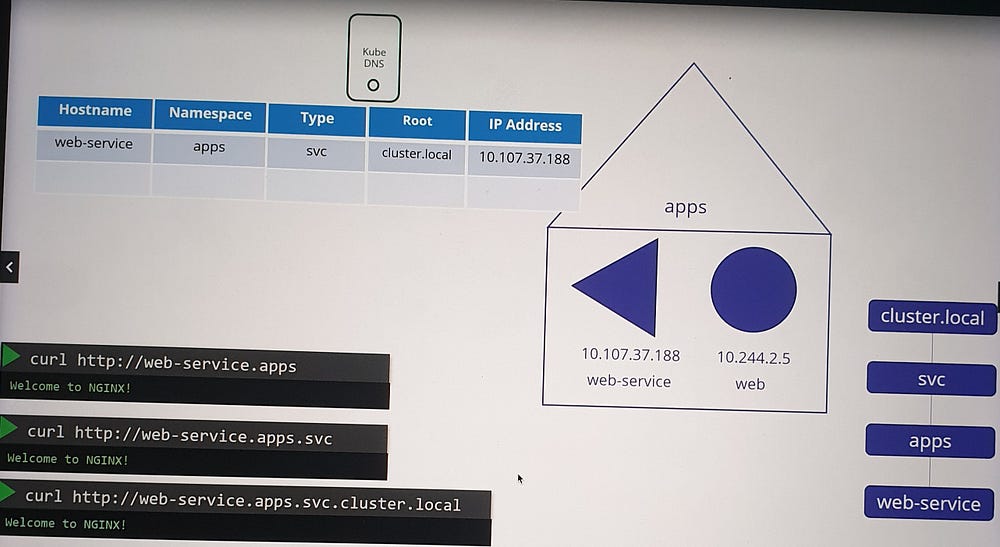
Example: DNS for Pods and Services
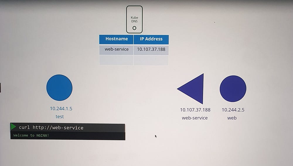
Scenario Setup
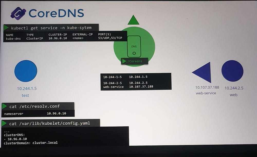
A test pod with IP
10.244.1.5.A web pod with IP
10.244.2.5.A web-service created to expose the web pod, assigned IP
10.107.37.188.
Service DNS Records
- When the service is created, Kubernetes automatically creates a DNS record for it.
- The service name (
web-service) is mapped to its IP address (10.107.37.188).
2. Pods in the same namespace (default) can access the service using its name, web-service.
Understanding Namespaces and DNS Resolution
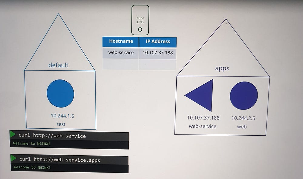
Within the Same Namespace
- Services and pods can be accessed using their first names (e.g.,
web-service).
Across Namespaces
To access a service in a different namespace:
Use the format
<service-name>.<namespace>(e.g.,web-service.apps).
Subdomains and Fully Qualified Domain Names (FQDN)
Kubernetes organizes services and pods within subdomains based on namespaces.
Services are grouped into an additional subdomain,
svc.By default, the cluster’s root domain is
cluster.local.A service’s FQDN is structured as:
<service-name>.<namespace>.svc.cluster.localExample:
web-service.apps.svc.cluster.local
DNS for Pods
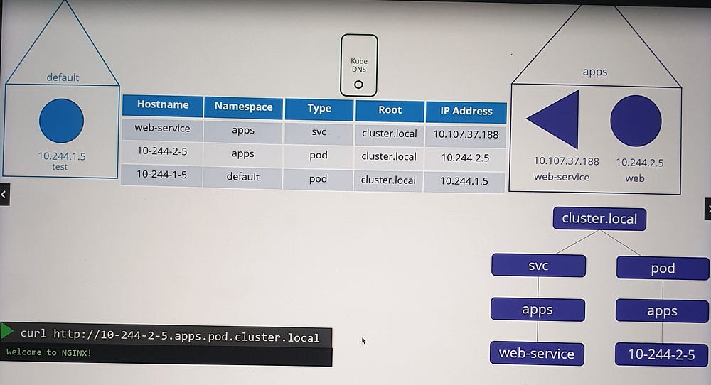
Pod Records
Pod DNS records are not created by default but can be enabled explicitly.
Kubernetes does not use pod names for DNS. Instead, it generates a name by replacing dots in the pod’s IP address with dashes.
Pod FQDN
- A pod’s DNS record includes:
The converted IP address as the hostname.
Namespace as a subdomain.
Root domain set to
cluster.local.
Example:
Pod IP:
10.244.1.5DNS record:
10-244-1-5.default.pod.cluster.local
This record resolves to the pod’s IP address.
How DNS Facilitates Communication
Services
Services provide stable names and IPs for accessing applications hosted on pods.
DNS ensures that any pod can access a service using its name, even if the service’s backend pods change.
Pods
- While direct pod-to-pod communication using DNS is possible, it’s less common. Services are typically used as intermediaries to abstract and manage backend pods.
***Core DNS in Kubernetes:
How Kubernetes Implement DNS?
In large clusters where thousands of pods are dynamically created and destroyed, Kubernetes centralizes DNS resolution through a dedicated DNS server.
Centralized DNS Server in Kubernetes
- DNS Resolution Mechanism:
Pods are configured to point to a centralized DNS server via their
/etc/resolv.conffile.The DNS server’s IP (typically
10.96.0.10) is specified as the nameserver.
2. Automated DNS Management:
When a pod or service is created, Kubernetes updates the DNS server with the appropriate DNS records.
Each pod’s
/etc/resolv.confis automatically configured to use the DNS server.
3. DNS Record Management:
Services get DNS records automatically.
Pods, however, only receive records if explicitly enabled via the Core DNS configuration (disabled by default).

Core DNS: The Default Kubernetes DNS Server
Starting with Kubernetes 1.12, Core DNS replaced the legacy kube-dns as the default DNS server. Core DNS is deployed within the cluster as:
A replica set with two pods for redundancy.
Located in the
kube-systemnamespace.
CoreDNS Configuration
- Core file:
Core DNS uses a configuration file named
Corefile, located at/etc/coredns.This file specifies plugins to handle various functionalities, such as:
Errors: Logging and handling DNS errors.
Health: Reporting the DNS server’s health.
Cache: Caching DNS responses.
Kubernetes Plugin: Integrates CoreDNS with the Kubernetes cluster.
2. Kubernetes Plugin:
Configures the cluster’s top-level domain, e.g.,
cluster.local.Manages DNS records for services and optionally for pods.
Converts pod IP addresses into dashed hostnames when the
podsoption is enabled.
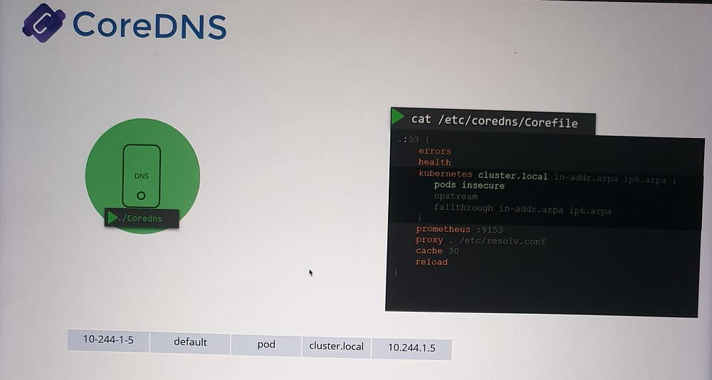
3. Forwarding Requests:
- If a DNS query cannot be resolved within the cluster, CoreDNS forwards it to the nameserver specified in its
/etc/resolv.conf.
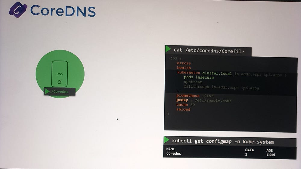
4. ConfigMap Integration:
- The
Corefileis managed via a ConfigMap, allowing dynamic updates to CoreDNS configuration without redeploying the pods.
DNS Configuration for Pods
- Service DNS Records:
Kubernetes automatically creates a service for Core DNS, typically named kube-dns.
This service assigns an IP (e.g.,
10.96.0.10), which pods use to resolve names.
2. Kubelet’s Role:
The kubelet is responsible for configuring each pod’s DNS settings when it is created.
The DNS server’s IP and the cluster domain are included in the kubelet’s configuration file.
Accessing Services and Pods
Service Name Resolution
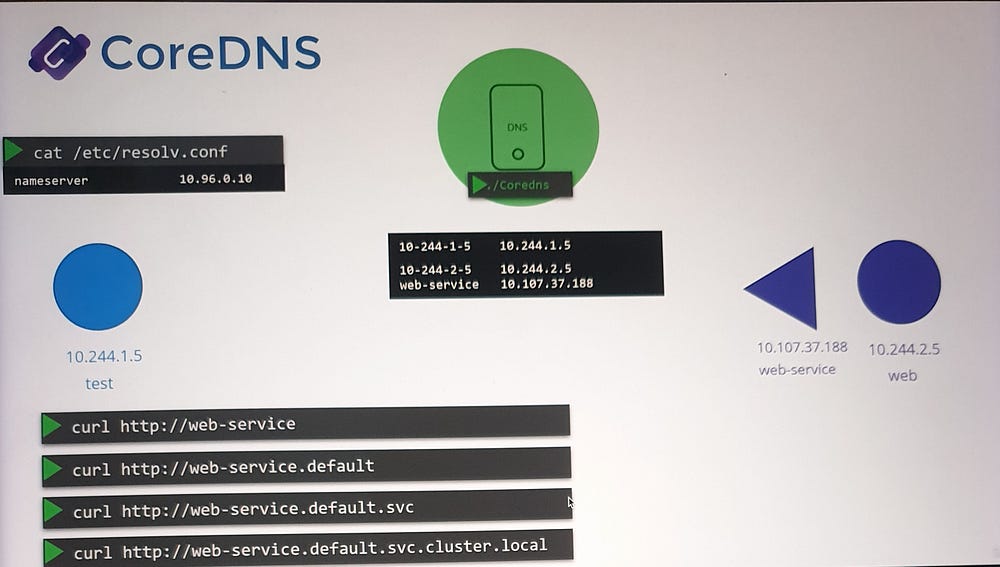
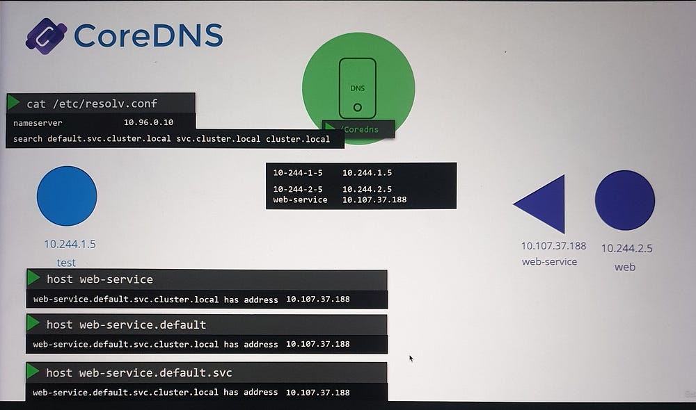
Services can be accessed using various formats:
web-serviceweb-service.defaultweb-service.default.svcweb-service.default.svc.cluster.local(FQDN)
Search Domains
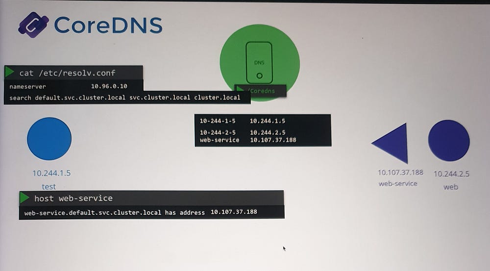
The
/etc/resolv.conffile on pods includes search domains such as:default.svc.cluster.localsvc.cluster.localcluster.local
These allow flexible resolution of service names without needing the full FQDN. For example, querying web-service will automatically append default.svc.cluster.local for resolution.
Pod Name Resolution
Pods do not get short-name DNS entries by default.
For pod name resolution, you must use the full FQDN (e.g.,
10-244-1-5.default.pod.cluster.local).
How DNS Works in Practice
- When a pod makes a DNS query:
The query is sent to the Core DNS service via the configured nameserver.
Core DNS checks its database for a matching record.
2. If a pod queries an external domain (e.g., www.google.com):
- Core DNS forwards the request to an external DNS server defined in its
/etc/resolv.conf.
3. For internal service queries (e.g., web-service):
- Core DNS resolves the name to the service’s IP and returns it to the querying pod.
***Ingress
Understanding Ingress in Kubernetes
What is the difference between Services and Ingress, and when should you use each?
Scenario: Deploying an Application
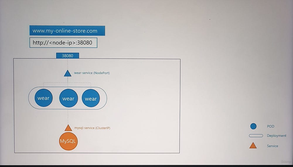
Imagine you’re deploying an online store application for a company that sells products. The application needs to be accessible at myonlinestore.com. Let’s break down the steps:

- Application Deployment:
Package your application as a Docker image and deploy it as a Pod in a Kubernetes Deployment.
The application uses a MySQL database, deployed as a Pod and exposed internally using a ClusterIP Service named
mysql-service.
2. External Access:
To expose your application to the outside world, create a NodePort Service, which makes the application available on a high port (e.g., 30880) on all cluster nodes.
Users can now access your application using a URL like
http://<Node_IP>:30880.
3. Scaling:
- Increase the number of Pod replicas to handle more traffic. The Service ensures traffic is distributed among these replicas.
Challenges with NodePort Services
- DNS and Port Management:
Manually managing IPs or high ports (e.g., 30880) isn’t user-friendly.
Configure your DNS to point to the Node’s IP, but users still need to include the port in the URL.
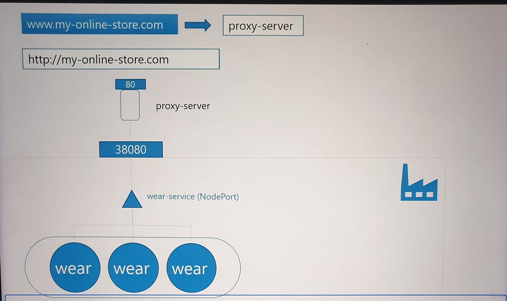
2. Proxy for Better Access:
Introduce a proxy server to route traffic on port 80 (standard HTTP) to the NodePort.
Users can now access your application at
myonlinestore.comwithout specifying a port.
3. Cloud Environments:
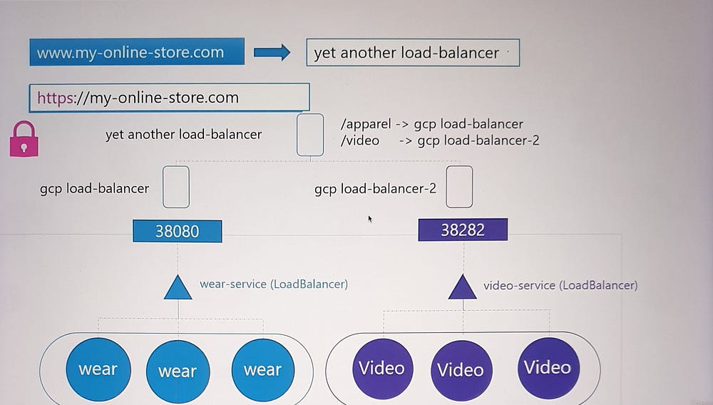
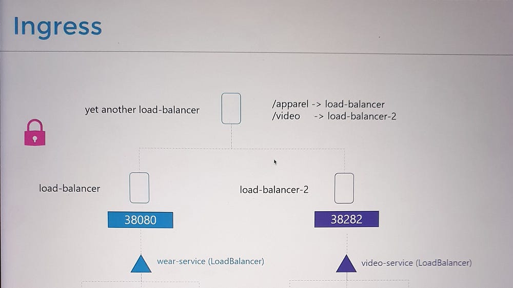
In a public cloud, instead of using NodePort, you can create a LoadBalancer Service.
Kubernetes requests the cloud provider (e.g., GCP) to provision a load balancer that routes traffic to your application.

Scaling Applications with Multiple Services
As the business grows, new services (e.g., video streaming at myonlinestore.com/watch) are introduced:
Deploy the new service as a separate Deployment and expose it using another LoadBalancer Service.
Each LoadBalancer incurs additional cost, and managing multiple external IPs becomes cumbersome.
To simplify this, you need a centralized mechanism to:
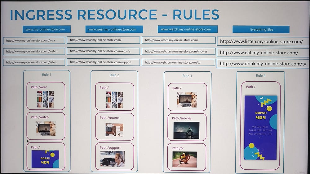
Route traffic to different services based on the URL (e.g.,
/watchor/shop).Enable SSL for secure communication.

Ingress to the Rescue
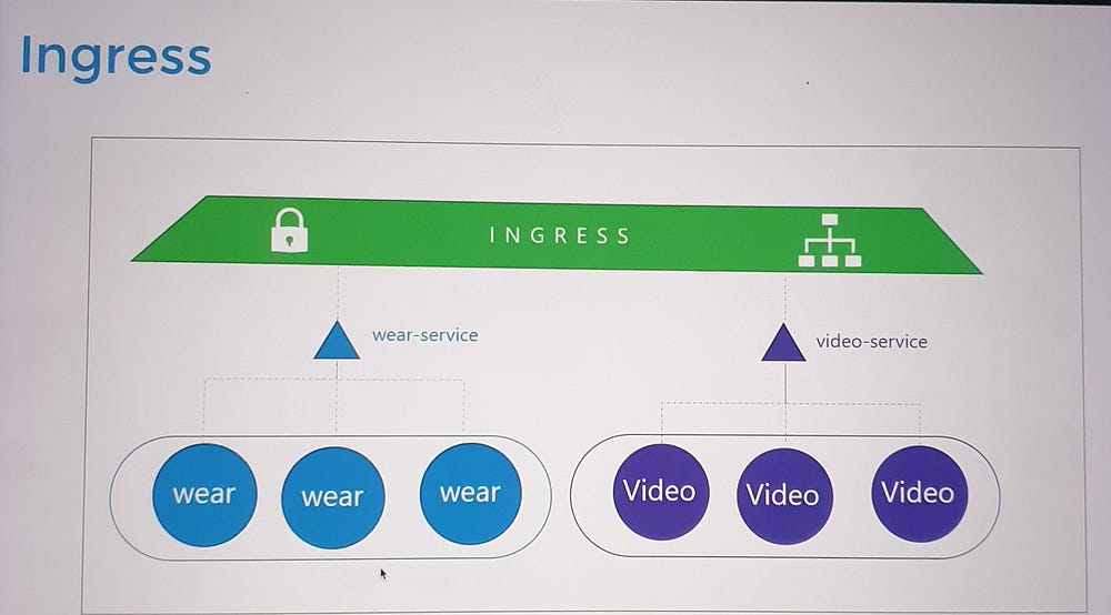
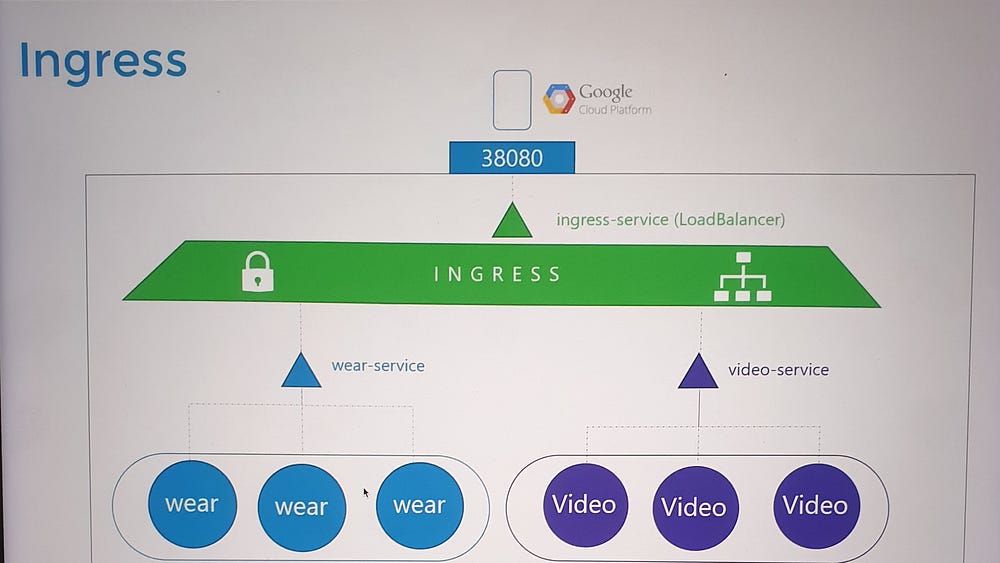
Ingress provides a unified solution:
Acts as a Layer 7 load balancer that can route traffic based on URL paths or domain names.
Manages SSL termination in one place.
Is defined using Kubernetes primitives, making it easy to version-control and manage alongside other Kubernetes resources.
How Ingress Works
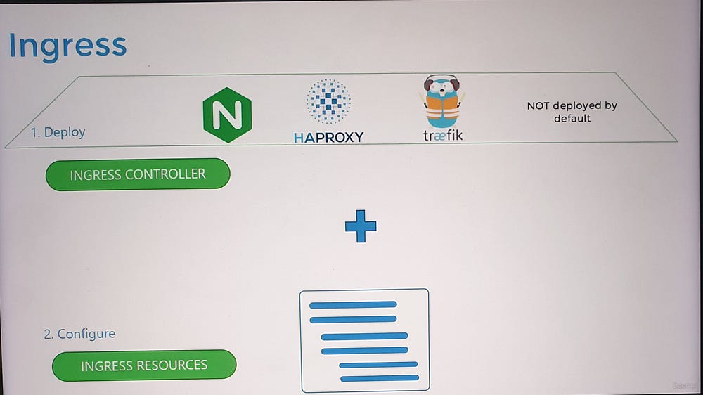
- Ingress Controller:
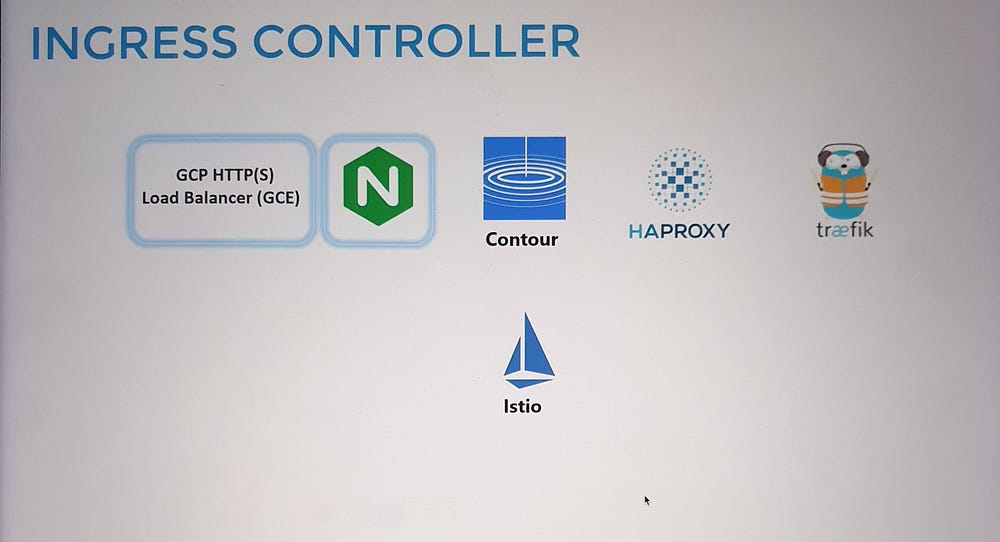
Ingress is powered by an Ingress Controller, which monitors the cluster for Ingress Resources (rules) and configures itself accordingly.
Popular Ingress Controllers include NGINX, Traefik, and GCE (Google’s HTTP Load Balancer).
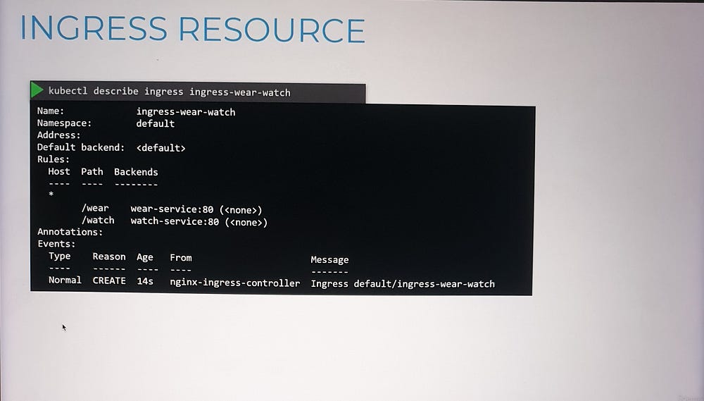
2. Ingress Resource:
- Specifies routing rules, such as forwarding traffic to specific services based on URLs or hostnames.
3. Configuration Example:
Route
myonlinestore.com/shopto theshop-serviceandmyonlinestore.com/watchto thevideo-service.Enable SSL and define a default backend for unmatched traffic (e.g., a 404 error page).
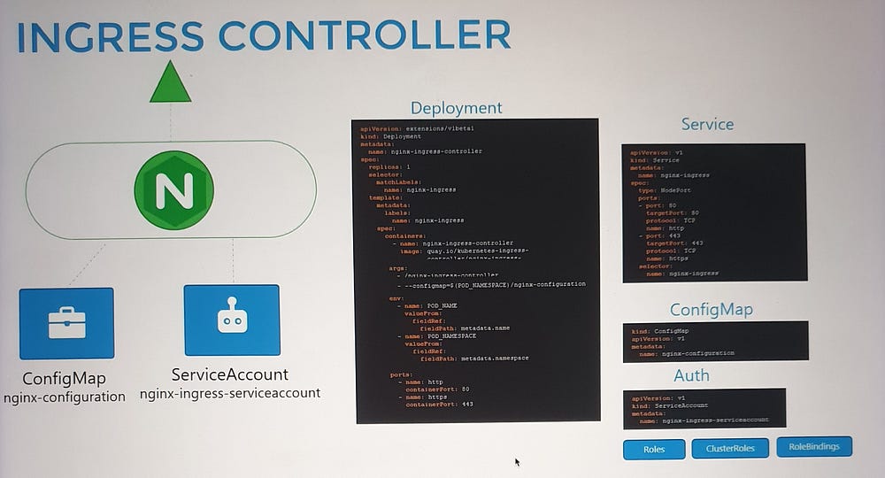
Deploying an Ingress Controller
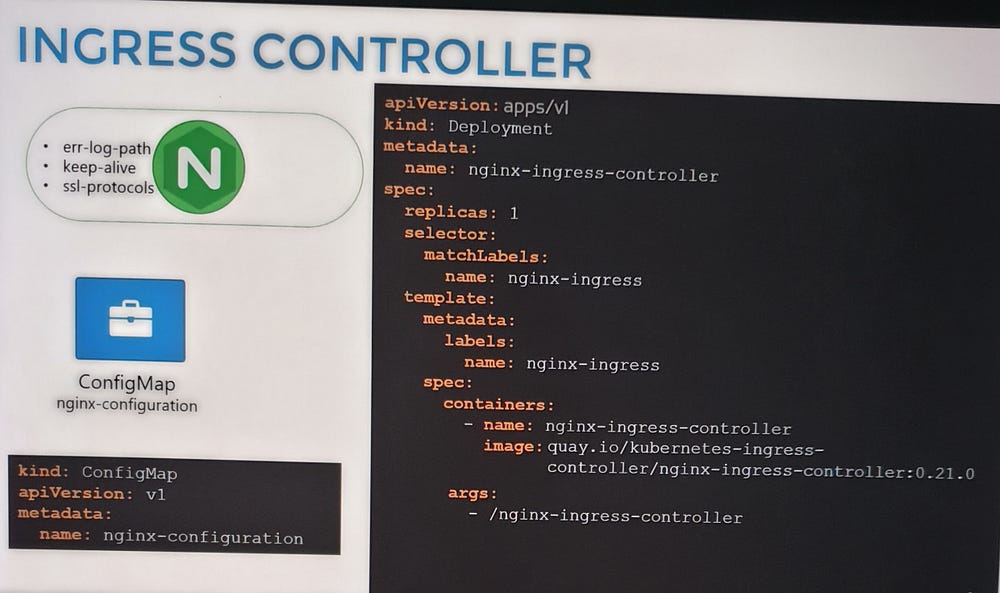
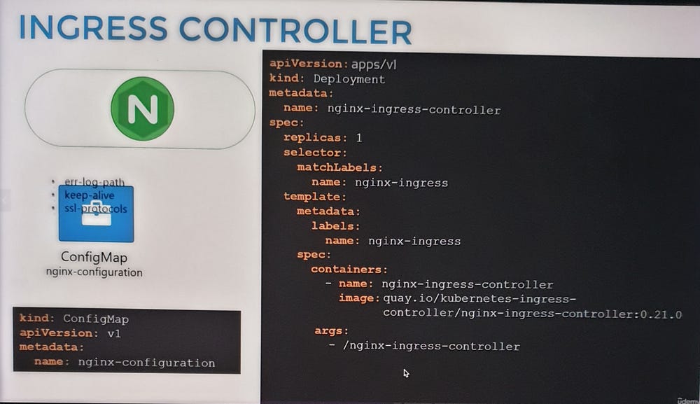
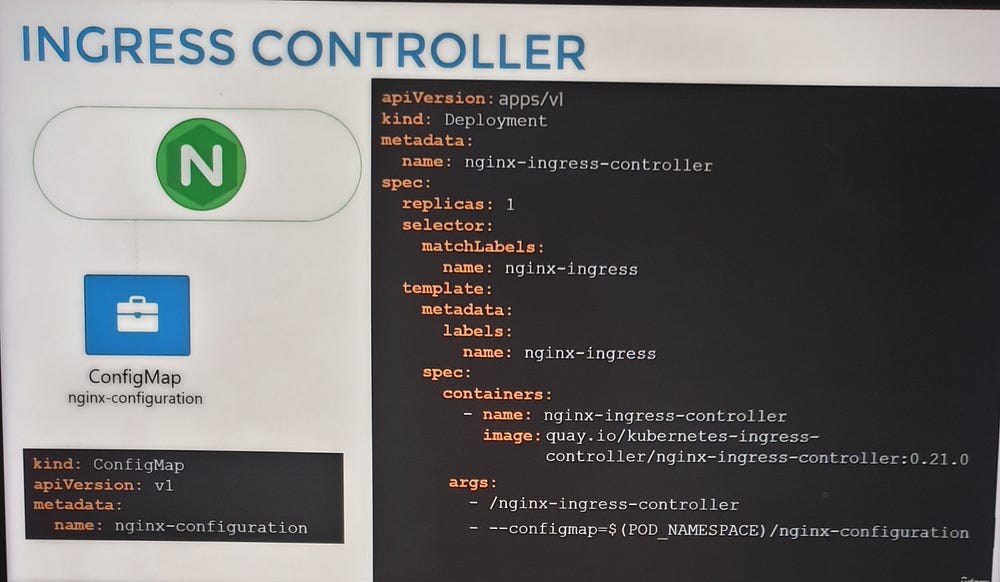
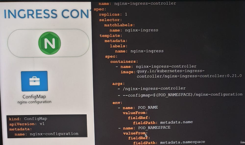
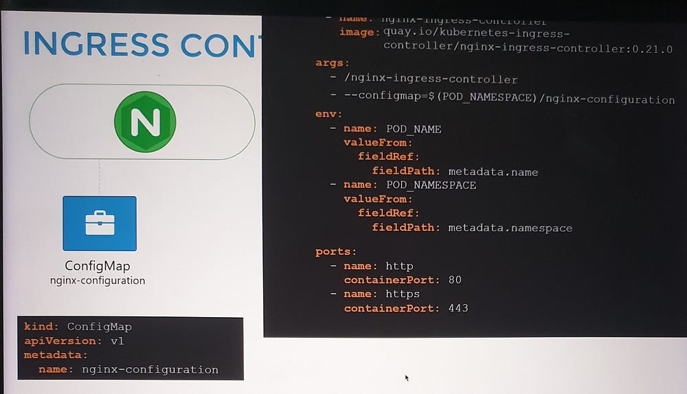
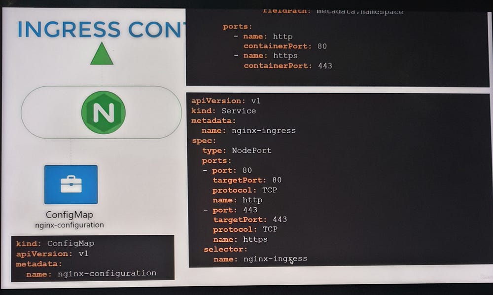
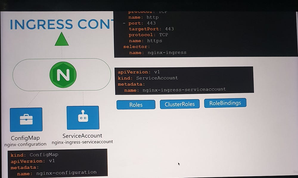
To set up an NGINX Ingress Controller:
Deploy the controller as a Deployment with the necessary image and configuration.
Expose it using a NodePort or LoadBalancer Service for external access.
Create a ConfigMap to manage NGINX settings.
Provide a ServiceAccount with the required permissions to allow the controller to monitor and manage Ingress Resources.
Configuring Ingress Resources
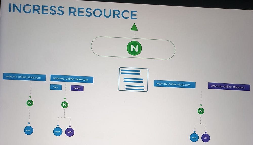
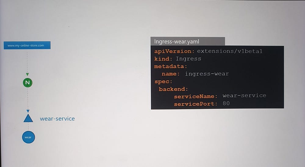
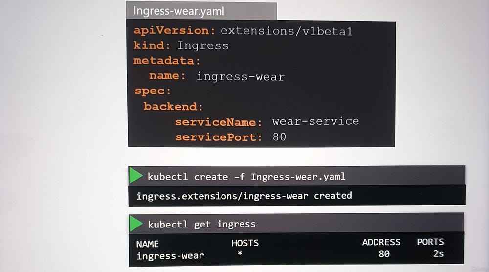
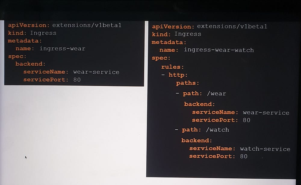
- Simple Routing:
- Route all traffic to a single service.
2. Path-Based Routing:
Define multiple paths within a single rule to route traffic to different services.
Example:
/shop→shop-service./watch→video-service.
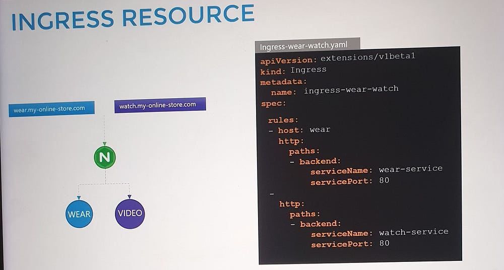
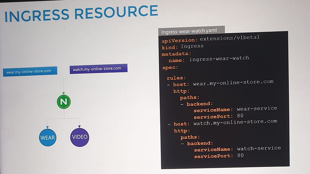
3. Hostname-Based Routing:
Use multiple rules to route traffic based on domain names.
Example:
shop.myonlinestore.com→shop-service.watch.myonlinestore.com→video-service.

🎉🎉In conclusion, Kubernetes redefines networking for modern application architecture with its innovative approach to services, load balancing and traffic management, empowering us to build scalable, secure and user-friendly applications.
